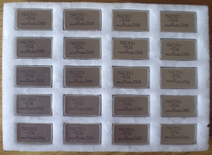
Since the Pinout was unavailable to me, too, I had to try and error here as well. The mechanical dimensions of the pins follow the ones of a 14-pin (DIP14) case style with only pin 1, 7, 8 ,9, and 14 present. By experimenting I could determine PIN 1 to be Vcc, Pin 7 to be GND, PIN 8 to be the modulation input, PIN 9 to be the control voltage, and PIN 14 to be the output.
Vcc should be 5 Volts. However, I experimentally applied up to 12 V without damaging the VCO. The control voltage should usually be between GND (0 V) and Vcc (5 V). With a control voltage between 0 – 5 Volts a total frequency deviation of ± 34 MHz around the center frequency can be achieved. If a control Voltage between 0 – 15 Volts is being used, the frequency deviation is -34 to +120 MHz around the center frequency. The output level is between -3 to 0 dBm into a 50 Ohm load.
The center frequency is indicated by the three digit suffix after the MCQ-501. For instance, a MCQ-501-836 has a center frequency of 836 MHz. I did not try out the sensitivity of the modulation input. Nonetheless these VCOs seem to be perfect for experiments in the 900 MHz amateur radio band.
If the power supply and the control voltage are fairly stable, just adding a regular PAL / NTSC video signal to the control voltage using a single capacitor would turn this VCO into a simple FM ATV transmitter. This is a quick and dirty approach of course as the transmitted signal contains no audio and lacks a proper pre-emphasis.
Westerhold, S. (2012), "Murata VCO MCQ-501: The missing datasheet". Baltic Lab High Frequency Projects Blog. ISSN (Online): 2751-8140., https://baltic-lab.com/2012/08/murata-vco-mcq-501/, (accessed: January 25, 2026).
- Conducted Emissions on the Bench: Implementing the CISPR 25 Voltage Method - December 15, 2025
- WebP-Images without Plugin - January 14, 2025
- Firewall Rules with (dynamic) DNS Hostname - January 14, 2025
