For my Direct Sequence Spread Spectrum Experiments I needed a simple circuit that creates a pseudo random bit sequence. Traditionally linear feedback shift registers (LFSR) are being used to generate a PRBS.
A linear feedback shift register (LFSR) is a shift register whose input bit is a linear function of its previous state. Usually two or more bits of the overall shift register value are exclusive-OR-ed and fed back into the shift register. The bit positions that affect the next state are called the taps.
If the taps are chosen wisely [2], a maximum-length linear feedback shift register is created. A maximum-length linear feedback shift register creates a bit stream with the maximum amount of different combinations possible with respect to the overall amount of bits in the shift register. In a maximum-length LFSR cycles through all possible 2n − 1 states within the shift register except the state where all bits are zero. An all zero state is usually prohibited because it would lock up the LFSR. This is because the XOR of all ‘0’s is still ‘0’. The XOR feedback does not produce a ‘1’ to get the sequence started again.
The picture shows a simple 7 stage PRNG. A 7-stage shift register can produce a maximal code with a length of 27-1 = 127 code bits. Those code bits are called ‘chips’ in spread spectrum terminology to stress that they are in no way part of any usable data. The output of the 1st and 7th bit are XOR-ed and fed back into the shift register. XOR-ing two bits is also called ‘modulo 2’ addition or / and subtraction. The reason is simply because XOR-ing two bits has the same result as adding and / or subtracting them without carrying over the next bit. To prevent the illegal all zero state, I added an inverter at the output of the XOR gate. A different approach to prevent an all zero state would be a 7 input AND gate that feeds back a logical 1 in the LFSR if all stages are zero.
The output sequence almost equals the statistical expectation value for a truly random sequence. The numbers have a nearly perfect bell shaped Gaussian distribution. However, LFSR are deterministic. If any given status of the shift register is known, the next state can be predicted.
The Gaussian bell shape can be visualized if the output of the PRNG is connected to a spectrum analyzer. The bell shape, which is distinctive for direct sequence spread spectrum signals, becomes apparent.
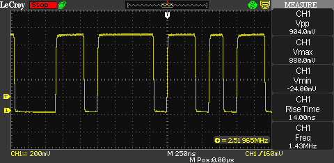
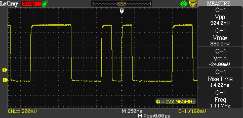
Here are two screenshots showing two different fragments of the pseudo random bit stream. The clock rate of the PRNG is 10 MHz.
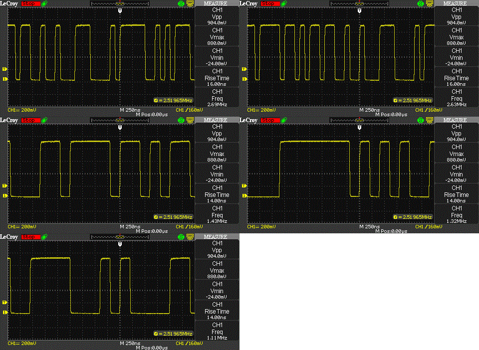
And here’s an animated GIF showing a few samples of the output signal. The clock rate is 10 MHz:
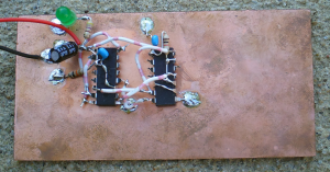
I didn’t actually use single D-Flip-Flops in my prototype. Instead I used a CMOS 4015 (dual 4 Bit shift register) and a CMOS 4030 (XOR). Two of the XOR gates are being used as an inverter. Any XOR acts like an inverter if one input is constantly being tied to a logic ‘1’ state.
UPDATE (10/29/2012): I replaced the oscilloscope screenshots with better ones from a LeCroy WaveAce 1002. Also replaced the picture of the CMOS PRNG with a better quality version.
Links and Sources:
[1] Book: Kesteloot, Andre (1991). Spread Spectrum Sourcebook. American Radio Relay League.
[2] Pseudo-Random Number Generation Routine for the MAX765x Microprocessor: http://www.maxim-ic.com/app-notes/index.mvp/id/1743
Westerhold, S. (2012), "Pseudorandom Number Generator (PRNG)". Baltic Lab High Frequency Projects Blog. ISSN (Online): 2751-8140., https://baltic-lab.com/2012/08/pseudorandom-number-generator-prng/, (accessed: January 14, 2026).
- Conducted Emissions on the Bench: Implementing the CISPR 25 Voltage Method - December 15, 2025
- WebP-Images without Plugin - January 14, 2025
- Firewall Rules with (dynamic) DNS Hostname - January 14, 2025


Closer look at a Direct Sequence Spread Spectrum Signal | KF5OBS /IP
[…] while back, I posted a Pseudorandom Number Generator (PRNG) for Direct Sequence Spread Spectrum (DSS) experiments. PRNGs are the key element in many […]