I stumbled across a box of ICS501 PLL clock multipliers from Integrated Device Technology and a bunch of PCBs I developed for them. The project dates back a few years when I needed an easy to build small clock multiplier. The multiplier was supposed to accept a regular through-hole and put out a frequency twice the crystal frequency.
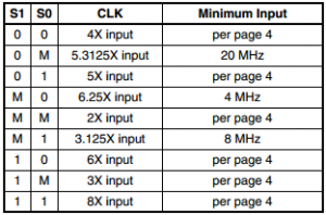
While designing that circuit, I stumbled across the ICS501. This tiny integrated circuit is extremely versatile. The IC has an inbuilt crystal oscillator, 9 different multiplication factors between 2 and 8, and promises a low jitter of 25 ps.
The IC is only available in an 8-SOIC package. Therefore, I designed the whole circuit around it with surface mount parts also.
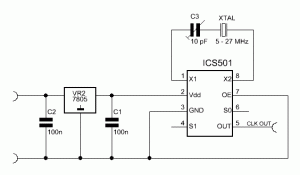
The circuit is pretty straight forward: a linear voltage regulator, the ICS501, a capacitor and of course a crystal – that’s all.
Being able to multiply frequencies between 5 – 27 MHz all the way up to 160 MHz opens up new options for the use of standard off-the-shelf crystals to generate higher frequency signals. Thanks to the decimal factors, we can now even achieve output frequencies which would have been impossible to generate from the same crystal frequency with discrete multipliers.
For instance, with a 23.16 MHz crystal, a multiplication factor of 6.25 and a small antenna on the output pin, we get an extremely simple 144.75 MHz 2m-band VHF tracking device suitable for direction finding exercises. The small device can even be modulated (FM) if we use a variable capacitance diode (varicap) instead of the trimmer capacitor and we inject a modulation signal.
Links and Sources:
[1] ICS501 Datasheet ICS501 Datasheet
Westerhold, S. (2012), "ICS501 - Integrated PLL Clock Multiplier". Baltic Lab High Frequency Projects Blog. ISSN (Online): 2751-8140., https://baltic-lab.com/2012/10/ics501-integrated-pll-clock-multiplier/, (accessed: January 21, 2026).
- Conducted Emissions on the Bench: Implementing the CISPR 25 Voltage Method - December 15, 2025
- WebP-Images without Plugin - January 14, 2025
- Firewall Rules with (dynamic) DNS Hostname - January 14, 2025


Crystal controlled listening device | KF5OBS /IP
[…] ICS501 – Integrated PLL Clock Multiplier […]
Jim DiGriz
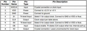
I believe Pin 7 is not held LO (i.e. 0), this puts it into a high impedance, rather I think it is left floating or HI (1) to enable the output.