PSK31 is a digital transmission mode with just about 31 Hz bandwidth. The signal conveys data at a data rate of 31.25 baud and is extremely robust even in weak signal conditions. 10 – 20 Watts of HF power is usually plenty for this mode. Let’s have a look at a PSK31 signal in the time domain.
PSK31 is used to transfer short text messages. The text that is supposed to be transmitted is being encoded varicode [1] prior to transmission. Varicode implements entropy encoding for lossless data compression. Entropy encoding simply means that characters used most frequently have shorter codes than characters used less often. The characters are seperated by binary ’00’. A space symbol for instance has the varicode ‘1’, the character ‘t’ has the varicode ‘101’, and the symbol ‘?’ has the varicode ‘1010101111’.
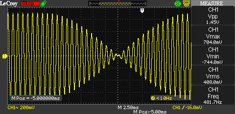
The most common type of PSK31 is BPSK31. As the name implies, binary phase shift keying (BPSK) is used for this sub-type. A binary ‘0’ causes a phase shift of 180 degrees on the carrier and a binary ‘1’ causes no phase shift. At a baud rate of 31.25 baud, this would result in an overall bandwidth of 62.5 Hz. To slash the bandwidth in half, the phase shifting occurs at an amplitude minimum and a raised cosine filter makes sure the amplitude transition is as bandwidth preserving as possible.
The following picture, shot with the Teledyne LeCroy WaveAve 1002, shows the 180 degree phase shift and the smooth amplitude transition:
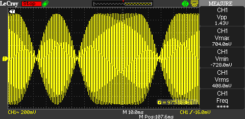
The next picture shows another another section of a BPSK31 signal. The carrier is a 1 kHz tone and the displayed data (starting after the first amplitude transistion) reads ‘00101’.
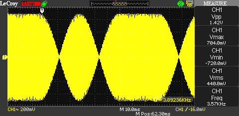
Here’s another screen capture of a BPSK31 signal. In this case the carrier frequency is 4 kHz and the displayed data seems to be ‘10010’.
Now that you know what a PSK31 signal looks like in the time domain, you can use this information to troubleshoot your PSK31 set-up. Ideally, the output of your transmitter should look exactly like the wave forms shown above. If for instance you send a BPSK31 signal with a carrier frequency of 1 kHz into a radio, which is set to 14.070 MHz upper sideband (USB), you should be able to see a signal at 14.071 MHz with the same signal properties as the signals shown above.
Be careful not to destroy your oscilloscope, they don’t usually enjoy high-power RF straight into their input ports. Make sure to terminate your radio with a proper 50 Ohm load capable of handling the expected RF power. And beware of the voltage levels, a 100 Watts RF signal into a 50 Ohms load already has a rms voltage of ~70 Volts. That is enough for a serious RF burn!
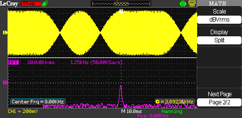
Another BPSK related phenomenon shows the following picture. The carrier frequency is again 4 kHz. The mixed domain mode of the LeCroy WaveAce 1002 is used here to display the signal both in the time domain (top) and in the frequency domain (bottom) at the same time. But where is the peak in the frequency domain? 8 kHz? What is wrong here?
The answer is simple: Nothing is wrong here. What the oscilloscope displays in the frequency domain is absolutely spot on. The 8 kHz peak is simply the harmonic of the original BPSK modulated 4 kHz signal.
Because the BPSK causes a phase shift of ± 180 degrees, the phase shift on the second harmonic would be ± 360 degrees. A phase shift of ± 360 degrees is practically equal to no phase change at all. That means the harmonic completely free of any phase modulation whatsoever.
This effect is used in a ‘squaring loop’ to recover the carrier. The received signal is being multiplied with itself (=squared) to generate a signal with twice the frequency of the original carrier but with the phase modulation removed. If the signal is then divided by two, the generated signal is phase-coherent with the original carrier and can be used to recover the data.
Links and Sources:
[1] Varicode, Wikipedia: http://en.wikipedia.org/wiki/Varicode
Westerhold, S. (2012), "Quick look at a BPSK31 signal". Baltic Lab High Frequency Projects Blog. ISSN (Online): 2751-8140., https://baltic-lab.com/2012/11/quick-look-at-a-bpsk31-signal/, (accessed: February 13, 2026).
- Conducted Emissions on the Bench: Implementing the CISPR 25 Voltage Method - December 15, 2025
- WebP-Images without Plugin - January 14, 2025
- Firewall Rules with (dynamic) DNS Hostname - January 14, 2025


