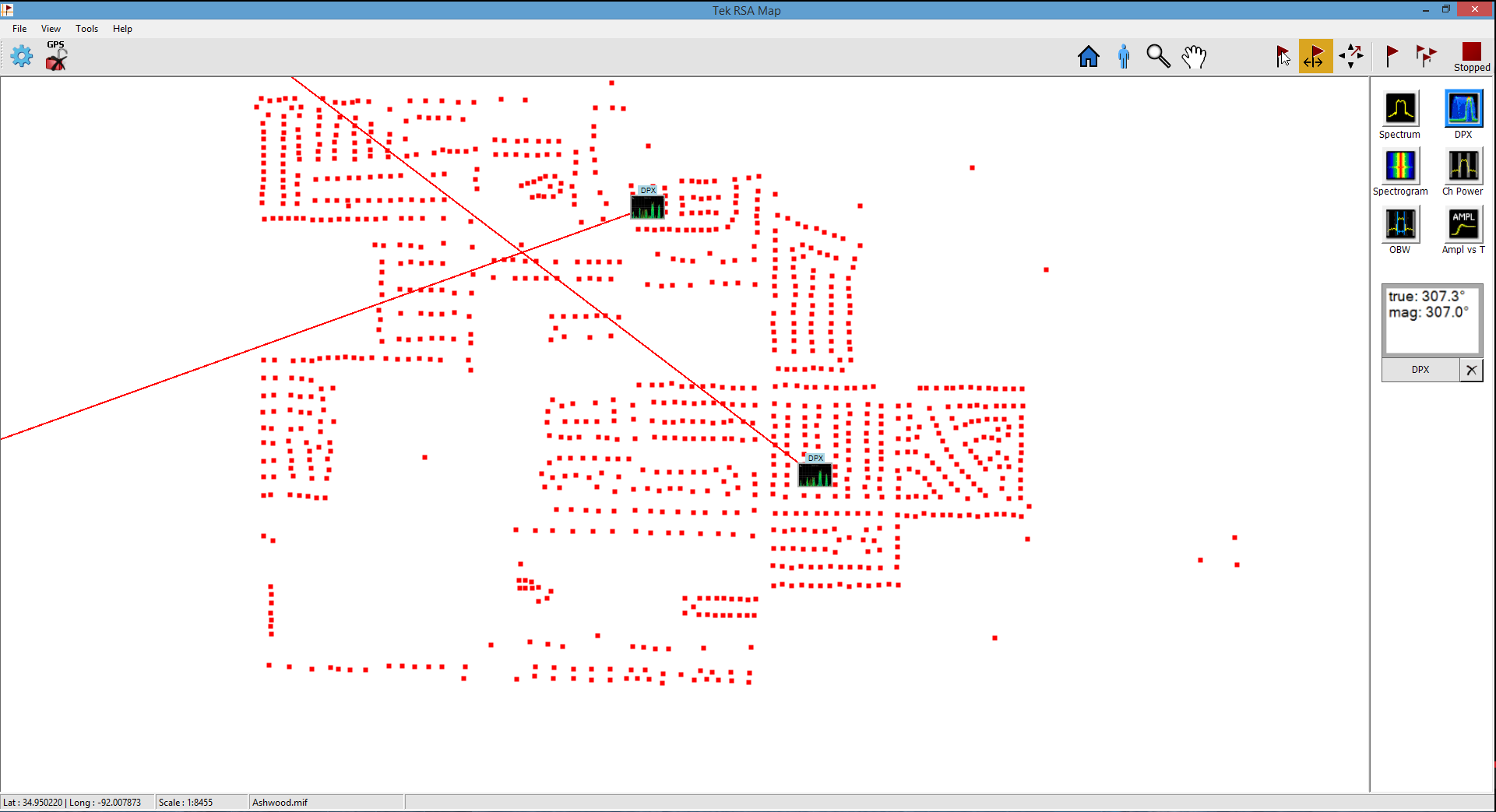
In recent weeks I had to do quite a bit of interference hunting for some government agencies such as a local volunteer fire department with harmful interference on their analog repeater network. When working with government agencies, one of the most important thing is documentation. One can’t just point antennas around ans say “I think it’s coming from that house over there.” This is obvious because this kind of interference will likely kick off some sort of enforcement action or even criminal sanctions if the interference is malicious and intentional. To fulfill this documentation requirement I used my RSA 306 spectrum analyzer, SignalVu-PC and RSA Map.
Since the temperature in the car and outside fluctuates quite a bit, I wanted to make sure that my frequency readouts are as accurate as possible. Especially right now where it’s icy cold outside and the car heater is on full throttle, it was apparent that the reference oscillator frequency would drift each time I would open the door to run a test with a directional antenna. Likely, this drift may not cause all too much trouble but I wanted to be absolutely spot on, especially since this was for government agencies. Since the RSA 306 has a connector for an external 10 MHz reference clock, this was a piece of cake to achieve.
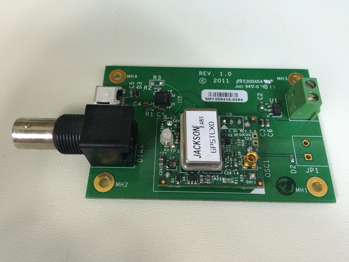
A perfect solution for supplying both the 10 MHz reference signal and GPS position information that was the GPS-Locked TCXO evaluation board from Jackson Labs that I reviewed about two years ago. This board served me very well as timing reference for my lab until it was recently replaced by a Jackson Labs Chip Scale Atomic Clock and an Analog devices PLL. The GPS-Locked TCXO board was perfect in many ways for this job. It’s small, USB-powered and inexpensive. The latter is important since items used in the field tend to get broken or lost.
CAUTION: The RSA 306 expects the level of the reference signal to be no greater than 10 dBm. That's 2 Vpp max. The GPSTCXO's output level is, however, 5 V CMOS level.
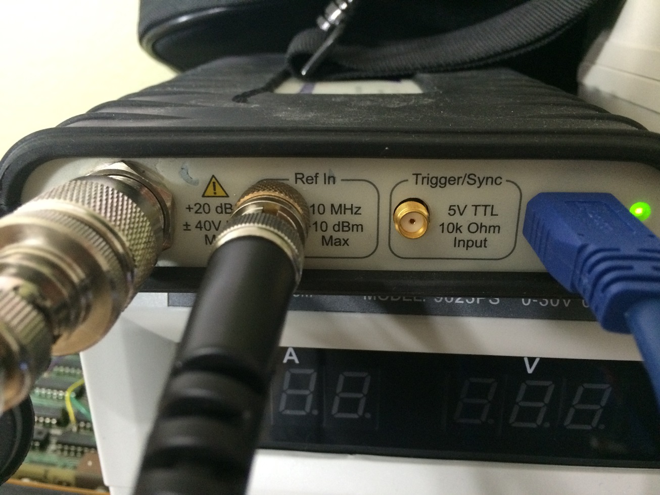
Despite the level difference, setting up the 10 MHz reference is a piece of cake; Simply connect the 10 MHz out from the GPSTCXO Evaluation board to the 10 MHz reference input on the RSA 306 through a 10 dB attenuator. The attenuator I used is a Mini Circuits HAT-10+.
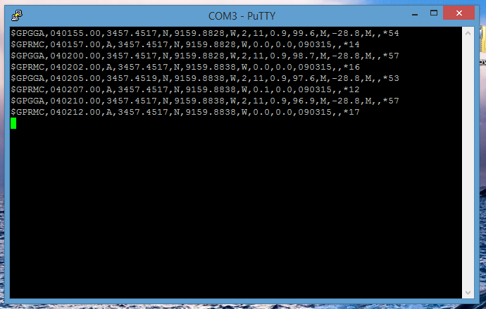
By default the GPS-Disciplined TCXO Eval board uses a baud rate of 115200 bps. For some reason the RSA Map software only supports speeds up to 38400 bps. Also, by default, the board doesn’t put out NMEA (=position information) data over the serial port. So we have to change the baud rate and set up the GPSTCXO board to spit out NMEA sentences periodically. These settings are modified by sending SCPI (Standard Commands for Programmable Instrumentation) commands to the board. To do this, you will have to use a terminal program to talk to the board and send commands. I used the freely available software Putty. Set the Terminal program to 115200 baud, 8 data bits, N parity bit, 1 stop bit. To verify that you are successfully connected, type the SCPI command “help?” or “syst:stat” (or any other valid command) and see if you get a reply. If everything went right, type the following SCPI commands, one after another and press enter after each line.
GPS:GPGGA 2

GPS:GPRMC 2

SYSTem:COMMunicate:SERial:BAUD 9600
The first two commands enable GPRMC and GPGGA NMEA sentences. The ‘2’ is the interval in which the system will provide us with updates, in this case 2 seconds. We don’t really need a high update rate at all. Even while driving around the county I don’t usually take snapshots more often than every minute or so. But if the NMEA sentence interval is set to anything less than 3, the RSA Map keeps switching back and forth between “GPS locked” and “GPS unlocked.” That’s why I left it at 2 to keep the software happy. After typing the first or second command, you should see NMEA messages being outputted into the terminal you are using to send commands. The last command obviously sets the baud rate. The Jackson Labs GPSTCXO Evaluation Board supports the following baud rates: 9600, 19200, 38400, 57600 and 115200 bps. I was somewhat surprised that it doesn’t support 4800 – a fairly standard speed for navigational receivers. But that doesn’t matter to us, pick any rate you please between 9600, 19200 and 38400 for compatibility with RSA Map. Remember to adjust your terminal’s baudrate to the new rate. Else you won’t be able to communicate with the board.
For an overview of all possible SCPI commands and setting I recommend you review the comprehensive user manual [2].
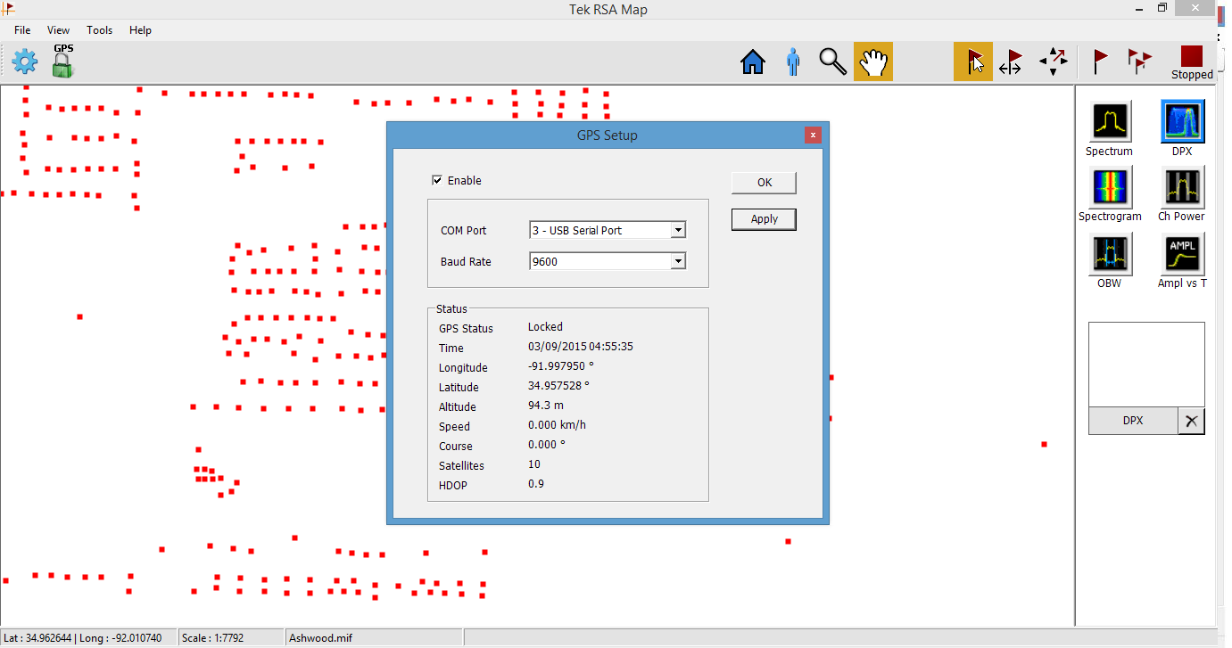
Now that we have the GPS receiver functionality of the GPSTCXO set up, we need to tell RSA Map where to find the navigation data. In order to do this you need to know the COM Port number and the baud rate you just set via SCPI command. Just enter it into the GPS Setup dialog, check “Enable” and hit “Apply”. If everything went right, valid GPS data should be displayed in the “status” section of the dialog. If so, click “okay” and start hunting interference
Just as a side note: This set-up of course also works with different Tektronix instruments such as the MDO4000(B) or the higher level RSA5000 / RSA6000 and SPECMON product line. While they are less portable, they do the job just as fine. And before the RSA306 was released to the market I would actually use my MDO4104B-6 in the car for interference hunting. When you power these instruments through an inverter, make sure it’s of high-quality. The last thing you want is a cheap power inverter to kill these sensitive instruments.
Links and Sources:
[1] Jackson Labs http://www.jackson-labs.com/
[2] Jackson Labs http://www.jackson-labs.com/
Westerhold, S. (2015), "Tektronix RSA 306 | GPS Receiver and Clock Reference". Baltic Lab High Frequency Projects Blog. ISSN (Online): 2751-8140., https://baltic-lab.com/2015/03/tektronix-rsa-306-gps-receiver-and-clock-reference/, (accessed: February 11, 2026).
- Conducted Emissions on the Bench: Implementing the CISPR 25 Voltage Method - December 15, 2025
- WebP-Images without Plugin - January 14, 2025
- Firewall Rules with (dynamic) DNS Hostname - January 14, 2025
John McCorkle
Your RSA306 teardown was terrific.
I was hoping you could do an addendum that was just a little more detailed, primarily just showing the signal paths used to cover 9 kHz to 6 GHz — i.e. through more of those SPDT switches. Or just post a more detailed block diagram.
For example, the Hittite HMC922LP4E is a differential SPDT switch that sits in front of the ADC. You showed one path, coming through the discrete filter, but nothing about the other path. Maybe it’s a low frequency direct-sample path? When you flipped the board upside down with the N connector on the top right, and you showed the initial signal path, there is a small inductor L2 that taps off a signal. Is that a low frequency bypass channel that covers 9kHz up to 40 MHz or so that comes back around to that 922 switch?
Similarly, you show an AD8343 mixer and AD4360 LO Generator combo, but no other mixer that allows coverage to 6 GHz. You mention the Maxim 2870 24MHz to 6 GHz synth. It clearly must make the LO to down-convert a 6 GHz signal, but your teardown did not show any path or paths using it, or the mixer that would use it.
What is that part that is labeled
MCL
-10
1231
Any chance you might post a new version that added more of these block diagram like details?
Thanks!
John
Sebastian
Hey John, thanks for your comment. The teardown of the RSA 306 was unfortunately done rather hasty and superficial. As a result I missed critical parts and my description of the circuitry was incomplete. Unfortunately, I can’t change that. I will, however, of course consider redoing a better and more complete teardown video.
Tektronix RSA 306 – GPS receiver and clock reference - Arduino collector blog
[…] KF5OBS writes, “The Tektronix RSA 306 is a great low-cost USB 3.0 spectrum analyzer for up to 6 GHz in an ultra low-profile format. If paired with the RSA Map function of SignalVu-PC and a GPS receiver, it becomes an extremely powerful tool for interference hunting and signal strength mapping. This article shows a possible way to supply position and timing information to the SignalVu / RSA 306 set-up from an external source.” […]