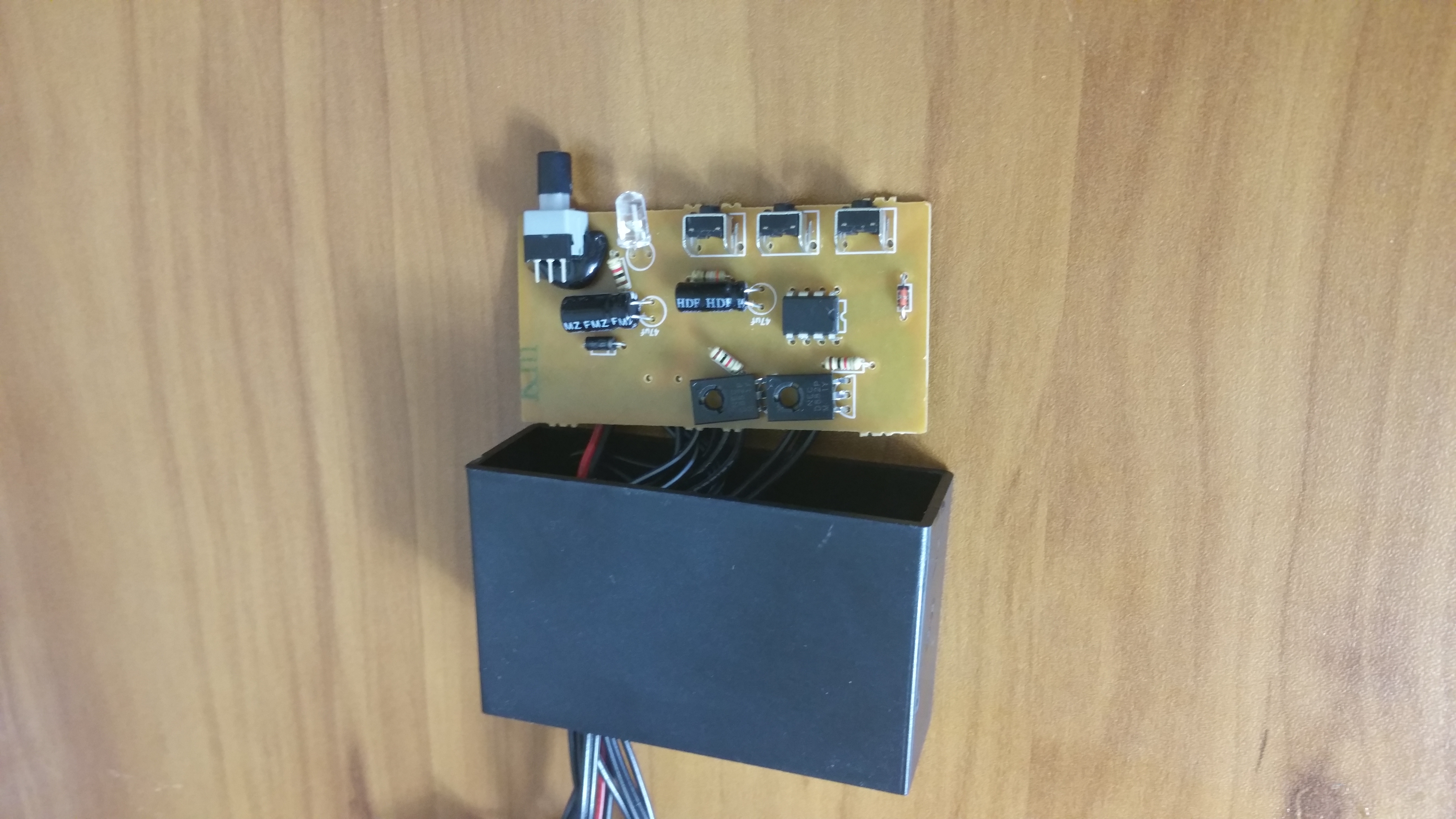
The strobe lights I purchased were white in color but they have the same kit in other colors like red, blue, amber, green and purple. Or a combination of those colors. The controller, however, remains the same regardless of color.
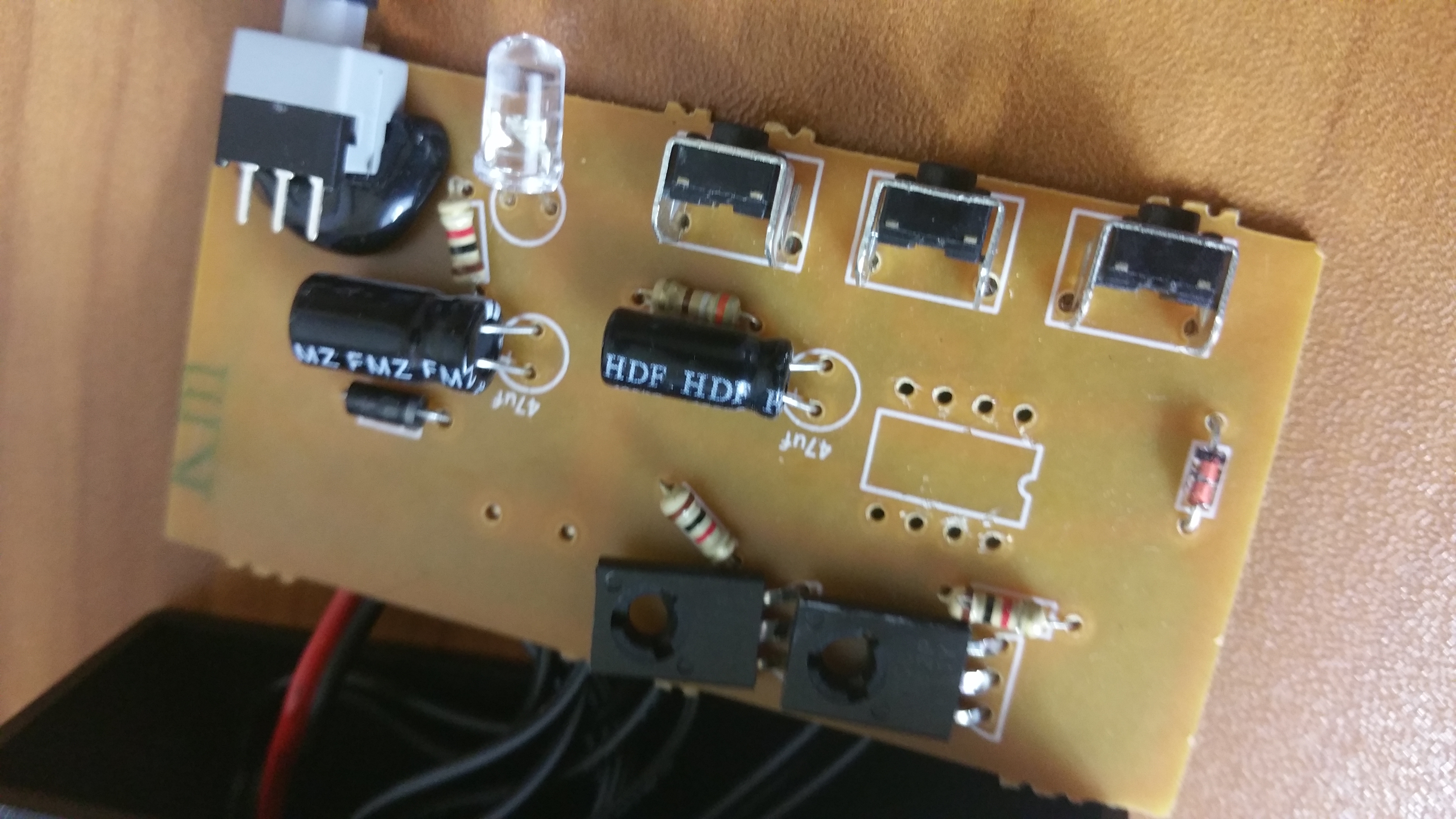
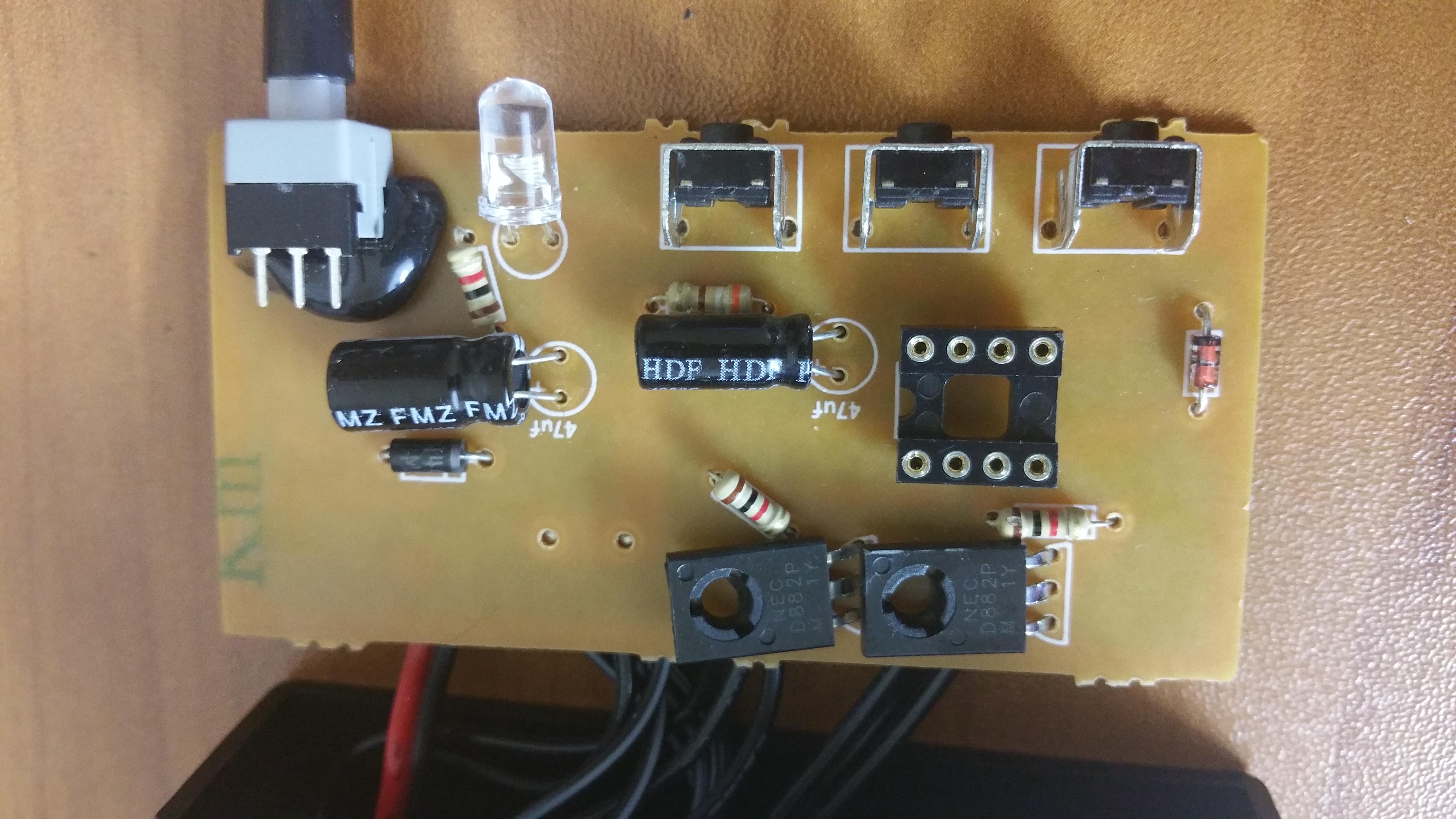
To hack this controller turned out to be way easier than ever expected. The on board IC and the ATtiny45 (or the tuny85) appear to have a similar pin layout. Vcc and GND are where they are supposed to be and the input and outputs make it straight onto I/O Pins. The only unfortunate thing is that the third button is connected to the pin corresponding to the Reset pin on the Atmel MCU. The reset functionality can be disabled, however, if you need that third input. I chose to use it in its function as a Reset to disable the strobing pattern. But first things first, this is what the controller looks like opened:
The first step is to remove the original IC. I cut all the pins of the IC and then carefully desoldered each pin individually using solder wick and vacuum suction.
To make programming and experimentation easier, I decided to solder a 8 pin IC socket in place of the old IC. You don’t have to use one if you don’t intent to change anything later on.
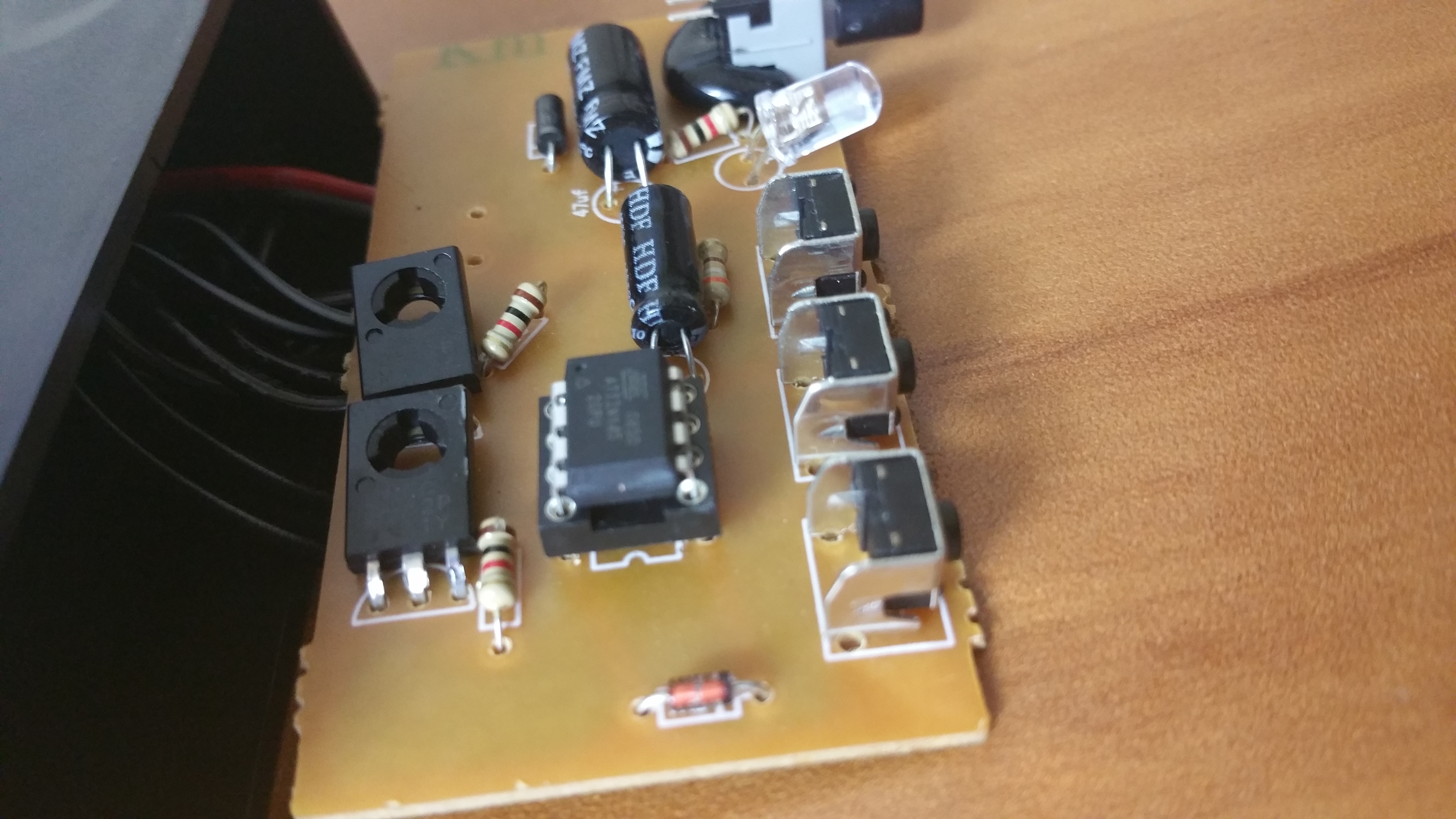
Lastly, the programmed ATtiny45 is inserted into the socket and the light show can begin. The software part is discussed further down int his article.
So what do the new strobing patterns look like you ask? Like this:
Let’s talk about the software. I wrote the few lines of code in BASCOM AVR. A demo version of BASCOM AVR is available for download on the internet. But of course you can write your own code using the Arduino or any other environment that supports ATtiny45s. If you don’t want to spend the time compiling this project, you can download the .hex and .bin files right here.
Here is the BASCOM code I used:
‘ Atmel ATtiny45
$regfile = "attiny45.dat"
‘ Fuse-bits 8 MHz int. div. by 8
$prog &HFF , &H42 , &HDF , &HFF
‘ 1 MHz internal clock
$crystal = 1000000
‘ PortB is Output
Config Portb.3 = Output
Config Portb.4 = Output
Config Portb.1 = Input
Config Portb.2 = Input
Config Portb.5 = Input
Pinb.1 = 1
Pinb.2 = 1
Dim Buff1 As Bit
Dim Buff2 As Bit
Buff1 = 0
Buff2 = 0
‘ Start flashing
Do
If Pinb.1 = 0 Then Buff1 = Not Buff1
If Pinb.2 = 0 Then Buff2 = Not Buff2
‘ Debounce
Waitms 25
If Buff1 = 1 Then Gosub Pattern1
If Buff2 = 1 Then Gosub Pattern2
Loop
Pattern1:
Portb.3 = 1
Portb.4 = 1
Waitms 125
Portb.3 = 0
Portb.4 = 0
Waitms 75
Portb.3 = 1
Portb.4 = 1
Waitms 125
Portb.3 = 0
Portb.4 = 0
Waitms 75
Portb.3 = 1
Waitms 75
Portb.3 = 0
Waitms 50
Portb.3 = 1
Waitms 50
Portb.3 = 0
Waitms 50
Portb.4 = 1
Waitms 75
Portb.4 = 0
Waitms 50
Portb.4 = 1
Waitms 50
Portb.4 = 0
Waitms 50
Return
Pattern2:
Portb.3 = 1
Waitms 75
Portb.3 = 0
Waitms 50
Portb.3 = 1
Waitms 75
Portb.3 = 0
Waitms 75
Portb.4 = 1
Waitms 75
Portb.4 = 0
Waitms 50
Portb.4 = 1
Waitms 75
Portb.4 = 0
Waitms 75
Return
Westerhold, S. (2015), "Hacking a Strobe Light Controller". Baltic Lab High Frequency Projects Blog. ISSN (Online): 2751-8140., https://baltic-lab.com/2015/12/hacking-a-strobe-light-controller/, (accessed: January 31, 2026).
- Conducted Emissions on the Bench: Implementing the CISPR 25 Voltage Method - December 15, 2025
- WebP-Images without Plugin - January 14, 2025
- Firewall Rules with (dynamic) DNS Hostname - January 14, 2025


