If you watched the video of Mike [1] from Mikeselectricstuff tearing down an Anritsu spectrum analyzer, you might have seen some weird shapes on the PCB that just don’t seem to make any sense. In case you missed the video, check out the last few minutes of it to know what I am referring to:
All pictures in this article are courtesy of Mike.
I am not going to explain the functionality of each and every circuit in great detail. As a matter of fact, I will try not to explain anything at all. Each circuit alone is enough for an individual article just on that type of RF circuitry. Therefore, I will add an article about every individual circuit shown here (and many more) shortly. The articles will contain much more detail including info on how to design them yourself.
Now let’s pick out some of the weird shapes on the PCB of Mike’s Anritsu spectrum analyzer and identify them.
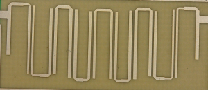
The first close-up is a hair-pin type band-pass filter. To keep it short, they are nothing else than loosely coupled LC resonators. Because parasitic capacitance and inductance is high enough to use them as filter elements in the GHz range, there are no actual discrete parts, such as inductors and capacitors, needed. Filters like this are called ‘distributed element filter’.
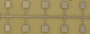
Next up is a distributed element low-pass filter. The rectangles on the top are capacitors and constitute a series resonator together with the vertically aligned strip-lines. Since series resonators are having a low impedance at their target frequency, they can be used as low-pass filters in this configuration. Basically what they do is sort out the unwanted signals at the resonance frequency of the series resonator.
The next picture shows a close-up of several radial stubs. They are extremely common to implement RF shorts that pass though DC voltages. Just like the aforementioned low-pass filter, radial stubs are nothing else than a series LC resonator. They have multiple applications. One is to notch out an unwanted signal. DC bias voltage PCB traces often have a radial stub on them to make sure no unwanted RF makes its way into the DC rail.
Okay, that’s the pre-tease for the upcoming Microwave Circuit Design 101 (MCD101) article series. This new series of articles will definitely serve a good experimental purpose; Either it will prove that RF circuit design is not at all black magic or it will prove that I a Voodoo master. I would feel comfortable with either outcome.
Links and Sources:
[1] Mikeselecricstuff: http://www.electricstuff.co.uk/
Westerhold, S. (2012), "Demystifying RF Circuit Design - The art of Voodoo". Baltic Lab High Frequency Projects Blog. ISSN (Online): 2751-8140., https://baltic-lab.com/2012/10/demystifying-rf-circuit-design-the-art-of-voodoo/, (accessed: December 28, 2025).
- Conducted Emissions on the Bench: Implementing the CISPR 25 Voltage Method - December 15, 2025
- WebP-Images without Plugin - January 14, 2025
- Firewall Rules with (dynamic) DNS Hostname - January 14, 2025


Paul Warmuth
I would love reading through this MCD101 when you are finished with it.
YS
I’m too! I’d love to read such a tutorial!
KF5OBS
As we move closer into winter, I will have more time for tutorials like the MCD101, so stay tuned.
Rakesh
Eagerly looking forward to MCD101
YS
So it seems that there’s still no MCD101 available (or am I missed something)? 🙂
By the way, last semester I had a course in microwave design, so now all those curves make much more sense to me. But still I’d not mind to read one more tutorial on this topic… 🙂
KF5OBS
You are correct, I have not gotten around to it. I had too many things to do and too little time in 2013. But this year I’ll focus more on the blog’s core topic, RF, and provide a whole lot more content than last year. I’m not certain yet if I will make the MCD101 as a text-blog article series or if I’ll utilize the video blog for that. I think especially the basics may be better on videos where I can show measurements and things like that much better. Just last week I gained a new sponsor for this blog, a manufacturer for microwave parts and modules. So stay tuned and make sure you subscribe to the YouTube channel as well.
YS
Text or video, that would be equally cool, because there’s not much information about microwave technology on the web.
So I’ll stay tuned for sure. 🙂
P.S.
Sorry for my possibly awful English, reading is much easier than writing, I should say. 🙂