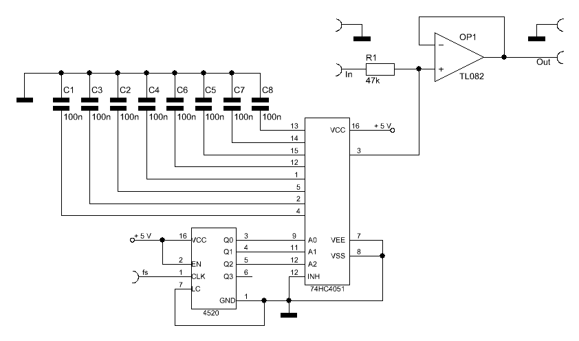
For a homebrew EAS (Emergency Alert System) decoder I needed a very selective band pass filter for the EAS Mark (2083.3 Hz) and space (1562.5 Hz) frequencies. For practical reasons I did not want to use a LC filter or implement digital signal processing in a microcontroller.
Classical band pass filter for audio frequencies are big and bulky. Since they are usually LC filters, they also require tuning due to parasitic capacitance and inductance. A software filter is overkill for such a simple job of demodulating a AFSK signal.
Thanks to switched-capacitor (SC) technology, I was able to design such a filter with just 2 CMOS ICs and an operational amplifier (op-amp) per tone.
The circuit above acts as a low pass filter and a band pass filter at the same time. The band pass cutoff frequency can be calculated by the following formula:
![]()
R is R1 (47 k Ohms), C is the value of each capacitor (100 nF), and N is the amount of stages (8). If we solve the equation with the given values, we get a cutoff frequency of 4.233 Hz.
The center frequency of the passband for the band pass filter function can be calculated as follows:
![]()
Therefore the center frequency of the passband is one eight of the filter clock frequency (fclk).
![]()
The 3 dB bandwidth of the band pass filter circuit with the aforementioned values is therefore two times 4.233 Hz, which is 8.466 Hz. That is an extremely small passband range and exactly what we need to extract a single tone.
Like all sampling systems, switched-capacitor (SC) filters are susceptible to aliasing [1]. Therefore the band pass properties of this filter repeat every whole number multiple of the first frequency (fc2). If the filter is clocked with 8 kHz for instance, the filter will not only pass signals with a frequency of 1 kHz but also 2 kHz, 3 kHz, etc. Because of this, the frequency response of a comb filter consists of a series of regularly spaced spikes, giving the appearance of a comb.
If that really bothers you, a simple low pass filter in front of the circuit can fix this issue and remove (or limit) unwanted whole number multiple responses.
With an appropriate clock source of 8 times the target frequency, this filter can be used for several different types of applications. For instance, the circuit can be used to extract CTCSS / DCS or 1750-Hz tones in 2-way radio applications.
Links and Sources:
[1] Aliasing, Wikipedia: http://en.wikipedia.org/
Westerhold, S. (2012), "Switched Capacitor (SC) comb filter". Baltic Lab High Frequency Projects Blog. ISSN (Online): 2751-8140., https://baltic-lab.com/2012/10/switched-capacitor-sc-comb-filter/, (accessed: December 15, 2025).
- Conducted Emissions on the Bench: Implementing the CISPR 25 Voltage Method - December 15, 2025
- WebP-Images without Plugin - January 14, 2025
- Firewall Rules with (dynamic) DNS Hostname - January 14, 2025
