A quadrature demodulator for FM signals consists out of two parts; A frequency dependent phase shift network and a phase detector. This article is going to take a closer look at the phase shifting network itself.
Two signals are considered to be in phase quadrature when their phase difference is exactly 90°.
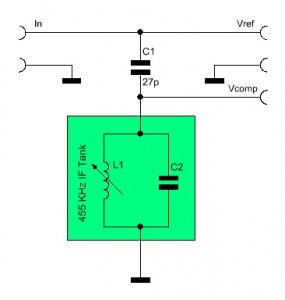
A quadrature detector splits the signal, that is to be demodulated, up into two signals. The first signal remains unchanged and is applied to the input of a phase detector. The second signals is passed through a capacitor. The capacitor will create a 90° phase shift. The phase shifted signal is then applied to a frequency dependent phase shifter, a LC tank circuit. If the LC tank circuits center frequency equals the signals frequency, it imposes a further phase shift of 0° on the signal. Therefore the overall phase difference will remain 90°.
If the signals frequency does vary from the LC circuits center frequency, the LC tank will further shift the phase of the signal from the capacitor, so that the signal’s total phase shift will be the sum of the 90° shift, that’s imposed by the capacitor, and the additional positive or negative phase change that is imposed by the LC tank circuit. If the frequency increases, the phase shift of the LC circuit decreases and vice versa. Therefore, the overall phase difference decreases as the frequency increases and vice versa.
If the the original signal and the phase shifted signal are applied to the input of a phase detector, the modulation signal (i.e. audio or data) can be recovered easily.
It would be a little bit unscientific to just believe those statements and trust they work. Lets use the above curcit to conduct a few experiments.
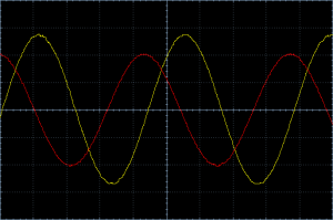
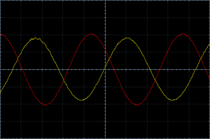
The LC tank circuit I used is a IF filter coil (a.k.a.: Intermediate Frequency Transformer) for 455 kHz. If we apply a signal with a frequency of 455 kHz we would expect an overall phase difference of 90° between Vref and Vcomp. To visualize the phase relationship I connected the signals to an oscilloscope and injected a 455 kHz signal with a signal generator. Vref is Channel 1 (red) and Vcomp is Channel 2 (yellow).
A whole cycle of the signal (360°) lasts 4.5 divisions. A fourth of it (90°) would be 1.125 divisions. And the picture indeed shows a distance of about 1.125 divisions between the two signals. You think it’s way too time consuming to count divisions and so some math? I agree, let’s use a fancy thing called a Lissajous curve [1].
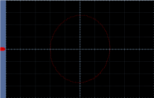
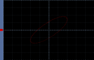
An oscilloscope is a very powerful instrument when it comes to visualizing the phase and frequency relationship of two signals. The oscilloscope needs to be operated in XY-mode instead of Time Domain Mode. It means that Channel 1 will control the X axis and Channel 2 will control the Y axis.
The Lissajous curve confirms our prediction: The phase difference is exactly 90 degrees.
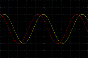
What happens if we increase the frequency to 458 kHz? We predicted that the overall phase shift will decrease. Let’s have a look on the oscilloscope:
We can tell already that the phase difference is smaller. Instead of counting divisions again, we can once again use the XY mode of the oscilloscope and get another Lissajous curve.
Thanks to the Lissajous curve we can immediately tell that the phase difference is 45 degrees. That is 45 degrees less than previously. That means that the change in phase difference (ΔΦ) is about 15° per 1 kHz change in frequency (Δf).
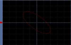
Now let’s try 453 kHz. Based on the results from our previous experiments, we would expect the phase difference to increase this time. Assuming ΔΦ is the same, we’d expect to see an overall phase difference of 135 degrees this time.
And sure enough, the Lissajous curve indicates that the phase difference between the two signals is 135 degrees.
Conclusion: If the frequency increases, the phase difference decreases. If the frequency decreases, the phase difference increases. In the range of 455 kHz ± 3 KHz the change in phase difference appears to be about 15 degrees per 1 kHz change in frequency.
Formula: ΔΦ = -15° * Δf
ΔΦ = Change in phase difference
Δf = Change in frequency
If we want to turn out circuit into a FM demodulator, we only need to add a simple phase detector. I explained in an previous article how an exclusive OR (XOR) gate based phase detector works.
A very sensitive FM demodulator based on the same principle is described in the article ‘No Tune NE602 / NE612 FM Demodulator’ [3].
Links and Sources:
[1] Lissajous-curve, Wikipedia: http://www.wikipedia.org
[2] Exclusive OR (XOR) gate based phase detector: https://baltic-lab.com/2012/09/exclusive-or-xor-gate-based-phase-detector/
[3] No Tune NE602 / NE612 FM Demodulator: No Tune NE602 / NE612 FM Demodulator
Westerhold, S. (2012), "How it works: Quadrature detector". Baltic Lab High Frequency Projects Blog. ISSN (Online): 2751-8140., https://baltic-lab.com/2012/09/how-it-works-quadrature-detector/, (accessed: January 27, 2026).
- Conducted Emissions on the Bench: Implementing the CISPR 25 Voltage Method - December 15, 2025
- WebP-Images without Plugin - January 14, 2025
- Firewall Rules with (dynamic) DNS Hostname - January 14, 2025
Exclusive OR (XOR) gate based phase detector | KF5OBS /IP
[…] How it works: Quadrature detector […]
No Tune NE602 / NE612 FM Demodulator | KF5OBS /IP
[…] How it works: Quadrature detector […]
John Smith
Hi,
I feel like an idiot, but I am still unclear as to what this would be used for. Please explain.
KF5OBS
Don’t feel like an idiot, it’s perfectly normal to not see the forest for the trees sometimes. It’s used to demodulate a FM signal. For instance, you could recover the audio from a FM broadcast station using this little circuit.
Chong
I think this is a good article.
Can you help to explain why with the frequency increase, the phase shift decrease, as below said in this article. Thanks!
” If the frequency increases, the phase shift of the LC circuit decreases and vice versa.”
Eli Duttman
An interesting thing is that quadrature demodulation of FM predates SS electronics. Check the 6BN6 gated beam tube out. A single active device amplifies, limits, and demodulates is (IMO) very impressive.
Check Dr. Adler’s paper out. http://r-type.org/pdfs/6bn6a.pdf
Eli D
QSO Today EPISODE 046 - TONY PARKS - KB9YIG SoftRock SDR creator
[…] Quadrature Detector – detector used in SDR radios. […]
Jed
Hi,
It’s a good article to explain what Quadrature detector is. However, I don’t know why it can be used in FM demodulation. Does the principle is that transfer frequency information to phase difference? thanks!
Hammy
Thanks so much. This post was really easy to follow and it was explained in terms that I understood. You’re simply the BEST.
<3