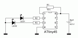
The circuit is very simple, two LEDs, 3 resistors and the microcontroller, that’s it. The Attiny45 has enough drive current (max. 40 mA) to drive even ultra bright LEDs directly [1]. R1 is a pull-up resistor for the RESET pin (Pin 1) od the ATtiny45. Resistors 2 and 3 are current limiting resistors and need to be calculated based on the LEDs used. They will usually range between 100 and 220 Ohms.
To calculate a matching current limiting resistor for a LED, simply subtract the forward voltage (VF) from the supply voltage of the circuit (4.8 V) and divide the result by the LEDs forward current (IF).
R = (Vdd – VF) / IF
I wrote the program for the microcontroller in Bascom AVR. The source code is extremely simple and self-explanatory. In case you do have any questions regarding the program, just drop me a few lines using the comment option below. An Archive containing the .bas source file for Bascom AVR and a compiled .hex file for other programmers can be downloaded here.
‘ Atmel ATtiny45
prog &HFF , &H42 , &HDF , &HFF
‘ 1 MHz internal clock
$crystal = 1000000
‘ PortB is Output
Config Portb = Output
‘ Start flashing
Do
Portb.3 = 1
Waitms 150
Portb.3 = 0
Waitms 100
Portb.3 = 1
Waitms 150
Portb.3 = 0
Waitms 150
Portb.4 = 1
Waitms 150
Portb.4 = 0
Waitms 100
Portb.4 = 1
Waitms 150
Portb.4 = 0
Waitms 150
Loop
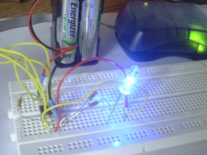
This is what the circuit looks like assembled on a breadboard. The Atmel AVRISP mkII programmer is still attached to it but is not necessary to operate the circuit.
And here’s a short Youtube video showing the flash pattern of the police strobe light:
Links and Sources:
[1] Atmel corporation, ATtiny25/45/85 Datasheet: http://www.atmel.com/
Westerhold, S. (2012), "Microcontroller Controlled Police Strobe Light". Baltic Lab High Frequency Projects Blog. ISSN (Online): 2751-8140., https://baltic-lab.com/2012/09/microcontroller-controlled-police-strobe-light/, (accessed: July 12, 2025).
- WebP-Images without Plugin - January 14, 2025
- Firewall Rules with (dynamic) DNS Hostname - January 14, 2025
- Restoring proxied visitor IPs from Cloudflare - December 26, 2024


Harish
Hello, The circuit looks very simple and the o/p was awesome! But can you design similar kind of LED blinking pattern without Micro Controller?
deep patel
CAN YOU TELL ME THE FUSE BITS AND CRYSTAL FREQUENCY FOR ATTINY 12L MICROCONTROLLER..
deep patel
and also sir tell me the fusebit and crystal frequency for atttiny13 microcontroller