Most audio listening devices, also called spy bugs, use simple oscillators with LC tank circuits as frequency determining elements. Their frequency is not even close to anything that could be considered stable. Despite the fact that many of those wannabe spy shops claim that they sell that sort of low-grade rubbish to authorities all over the world, those devices are virtually useless in a real life scenario.
More accurate listening devices derive their carrier frequency from a vibrating crystal of piezoelectric material. Crystals are suitable to create an electrical signal with a very precise frequency. With an integrated PLL clock multiplier like the ICS501 [1], we can easily build a crystal-controlled listening device ourselves.
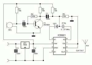
The ICS501 is hardwired to a multiplication factor of 6.25 (S0 = Ground, S1 = Open). There’s a bunch of standard crystal frequencies available which will result in a practical VHF frequency if multiplied by 6.24. For instance, the standard frequency 23.16 MHz results in an output frequency of 144.75 MHz (2m amateur radio band). The following standard crystals are suitable for transmissions in the FM radio band (88 – 108 MHz): 16.128 MHz (100.8 MHz), 16.384 (102.4 MHz), 16.9344 (105.84)
The crystal’s frequency is being pulled slightly off target by the variable capacitance diode (CD1). The control voltage is biased by R3 and R5 to about 2.5 V. The audio entering the electric microphone (MIC) is being amplified by T1 and then applied to the variable capacitance diode (CD1) by C1. The change in voltage across CD1 will alter the capacity of CD1. As a result, the frequency of the oscillator is altered.
The circuit is pretty sensitive because the change in frequency of the crystal oscillator is also being amplified by factor 6.25. 160 Hz of change in frequency of the crystal oscillator and will therefore result in 1 kHz deviation of the output signal.
One thing that is somewhat problematic to get nowadays is a variable capacitance diode. I used a NTE618, which is available for $ 3.11 from Newark [2], and a 30 pF capacitor in series in my assembly.
Real audio surveillance circuits used by authorities nowadays rely on the cell phone network to bring the audio back to the corresponding agency. The times of a surveillance truck with a bunch of high ranking surveillance technicians in front of the target’s house is far from over. But just as much as the myth of a ‘clicking noise’ on a tapped phone line, this sort of outdated ‘knowledge’ will probably stick around for another few centuries.
Links and Sources:
[2] ICS501 Clock Multiplier, Jaunty Electronics: http://baltic-lab.com
[2] NTE618, Newark: http://www.newark.com/
Westerhold, S. (2012), "Crystal controlled listening device ". Baltic Lab High Frequency Projects Blog. ISSN (Online): 2751-8140., https://baltic-lab.com/2012/10/crystal-controlled-listening-device/, (accessed: January 19, 2026).
- Conducted Emissions on the Bench: Implementing the CISPR 25 Voltage Method - December 15, 2025
- WebP-Images without Plugin - January 14, 2025
- Firewall Rules with (dynamic) DNS Hostname - January 14, 2025

Darren
Hello
Very nice work.
Have you any more information or pictures
on the Crystal controlled listening device using the
ICS501 IC.
I have some ICS501 in my bit box and will like to build
this listening device using the ICS501 IC.
Please send to my email address at [email protected]
Many thanks in advance.
Darren
KF5OBS
Darren, this is an older project I just recently had the time to write up. I will check what I still have laying around in my boxes and will check back with you. What I do know though is that I still have a bunch of PCBs for my similar ICS501 clock multiplier project (https://baltic-lab.com/2012/10/ics501-integrated-pll-clock-multiplier/). If you think a few of those would help your experiments, I can stick some in an envelope and send them your way.
Rex
Hi there!! I found your excellent page as I was browsing the internet for a crystal locked bug. The project of yours seems promising and low part count. I wonder how it performs… Is there any layout or PCB pattern that you can email to me?
best regards, Rex.
A. Genchev
Interesting schematic, thanks. NXP/Philps make varicaps, wouldn’t it work with BB179 ?
ionut
range…?