The MRC DAR Plus series transmitter / receiver are professional devices for studio-transmitter links (STL), transmitter-studio links (TSL), ENG back-haul, and intercity relays [1]. They operate in the 7 GHz and 13 GHz Broadcast Auxiliary Service (BAS) frequency band.
One DAR Plus receiver at a local TV station was deemed broken. The symptoms were no IF output (except noise). A different receiver in place of the broken one worked fine. After opening it, I was fairly surprised of how modular this whole device is.
The device is designed very simple, a YIG type local oscillator (LO), a mixer, a band-pass filter and an IF amplifier with Automatic Gain Control (AGC) – that’s pretty much everything in the box aside from the power supply. They even use the same oscillator for 6 and 13 GHz, a simple x2 multiplier makes this possible. The modules are easily accessible. They are connected with SMA type connectors through small jumper cables.
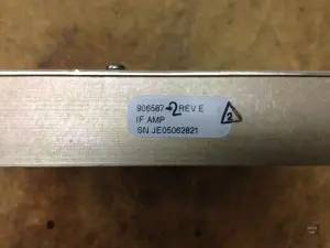
Knowing that there was no IF output whatsoever and the noise floor did not change when connecting or disconnecting the rest of the circuitry to the input of the IF amp, I immediately suspected this module to be broken.
After taking the module out of the DAR Plus, I connected the input of the IF amp to a signal generator and hooked the output up to a spectrum analyzer. And sure enough, there was no change in the output noise floor when applying a 70 MHz signal to the input of the IF amp. The next step was to take a look inside to see if it would even make sense to investigate any further.
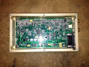
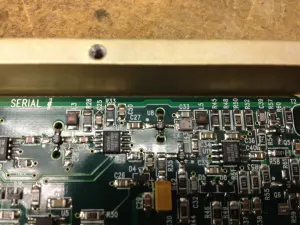
The PCB is completely designed in Surface Mount Technology (SMT) using Surface Mount Devices (SMD). The round things with 4 legs are MMICs (Monolithic Microwave Integrated Circuit). They are basically highly integrated RF amplifier. I injected a 70 MHz signal again and followed the signal from one MMIC to the next. And suddenly after one MMIC, there was no signal anymore. The MMIC had to be the problem.
The marking of the MMIC is N02. That translates to an HP INA-02186 [2]. I got a few of those from eBay for about $1 each including shipping.
After carefully replacing the MMIC on the PCB, I tested the IF module by applying a 70 MHz signal again. This time the signal made it through all the way to the output as expected. So I put the case back together and installed the module in the DAR Plus receiver. And, as expected, the thing started working again.
And what do we learn from this? Never assume something can’t be fixed in-house. Any TV station should be able to to this themselves. And if you don’t have the necessary equipment, that’s also fine. Ship the device to me, I’ll fix it for a fraction of what the manufacturer would charge you.
Links and Sources:
[1] MRC DAR Plus, Vislink: http://www.vislink.com/documentation/datasheets/broadcast/DARPlus-2.pdf
[2] INA-02184, HP: http://www.datasheetcatalog.org/
Westerhold, S. (2012), "Repairing a MRC DAR Plus Receiver". Baltic Lab High Frequency Projects Blog. ISSN (Online): 2751-8140., https://baltic-lab.com/2012/10/repairing-a-mrc-dar-plus-receiver/, (accessed: January 19, 2026).
- Conducted Emissions on the Bench: Implementing the CISPR 25 Voltage Method - December 15, 2025
- WebP-Images without Plugin - January 14, 2025
- Firewall Rules with (dynamic) DNS Hostname - January 14, 2025


Chris
Now that you have fixed one you will be surprised how similar they all are. MMIC failure is very common and as you have found, fairly easy to track down. Many times the MMICs are from minicircuits and easy to get.
Good luck. I love repairing RF stuff. Have fun.
Darel Vanderhoof
For the DAR, and Twinstream, you can replace the MRC YIG synthesizers with a Microwave Dynamics PLO-3000 DRO. Basically its a drop in; mount it, and size an output attenuator for it. Have not tried in DAR+.