I have no idea if that was just my perception or if the year 2012 was the year of the oscilloscope revolution. An incredible flood of new scopes was released into the market in 2012. There’s the Agilent InfiniVision series, the Tektronix MDO4000 series, the Rigol 2000, and the Teledyne LeCroy HDO4000 and HDO6000 series.
Teledyne LeCroy sent me one of their 6000 series High-Definition Oscilloscope (HDO). To be precise, it’s the HDO6054, a 12-bit, 500 MHz oscilloscope. A product like this deserves a thorough review. With my usual review style, the length of the review would exceed the length of the bible. But before I even start to write the review, let’s talk about 12-bit vs. 8-bit.
First, movie time. Let’s watch the official video LeCroy used to announce their HDO4000 and HDO6000 series scopes:
I was very surprised about the way Teledyne LeCroy presented their new scope. Aside from stating some apparent facts in a humorous and authentic way, there was no typical US marketing buzzword bingo present at all. I like it. That being said, let’s talk about 12-bit.
8-bit or 12-bit resolution, what does that even mean? A digital scope measuring an analog signal logically needs a circuit translating between the realms of the analog and digital world. An analog-to-digital converter (abbreviated ADC, A/D or A to D) is needed to allow the digital circuitry of a modern scope understand the analog input. The root of the word digital is the Latin word for ‘finger’, digitus. This is because digital systems can only indicate whether or not a bit is set (1) or not (0), kind of like counting with your fingers. There are only 256 (28) different values that can be represented with an 8-bit variable. That means if the maximum permissible input range of an ADC is 0 – 5.12 V, the maximum resolution would be 20 mV. That means the ADC can’t tell the difference between two signals whose difference is smaller than 20 mV very well. The ADC rounds up and down in between full 20 mV steps.
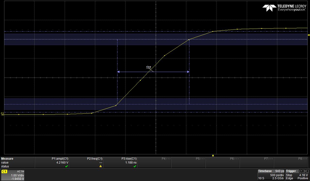
Rise time measurement with markers on the HDO 6054
12-bit means 4096 possible values. Assuming the same input range, we now get 1.25 mV resolution. That’s obviously much better. Critics argue that one is not able to utilize the full 12-bit in a real world application due to quantization noise among other things. But let’s not get into that discussing now, it’s enough material for a whole new article.
Another term often heard in relation to 12-bit technology is “dynamic range.” To understand dynamic range, we must first understand how an oscilloscope applies a signal to the ADC. In my above example, I chose an ADC with 0 – 5.12 V input range. The number is arbitrarily picked for easy math. Now let’s a assume a saw tooth-shaped signal with a peak at 512 mV is applied. With 8-bit resolution, the ADC would turn the smooth upwards slope into 20 mV steps. The ADC could not understand that it is dealing with a linear increase but would indeed see a stepped response. To circumvent this problem, oscilloscopes include a Variable Gain Amplifier (VGA). The smart circuitry makes sure that the ADC is always driven to the max. In the case of our saw-tooth signal, an amplification factor of 10 would be just fine. The ADC could now detect steps as small as 2 mV because after amplification they are going to be 20 mV steps.
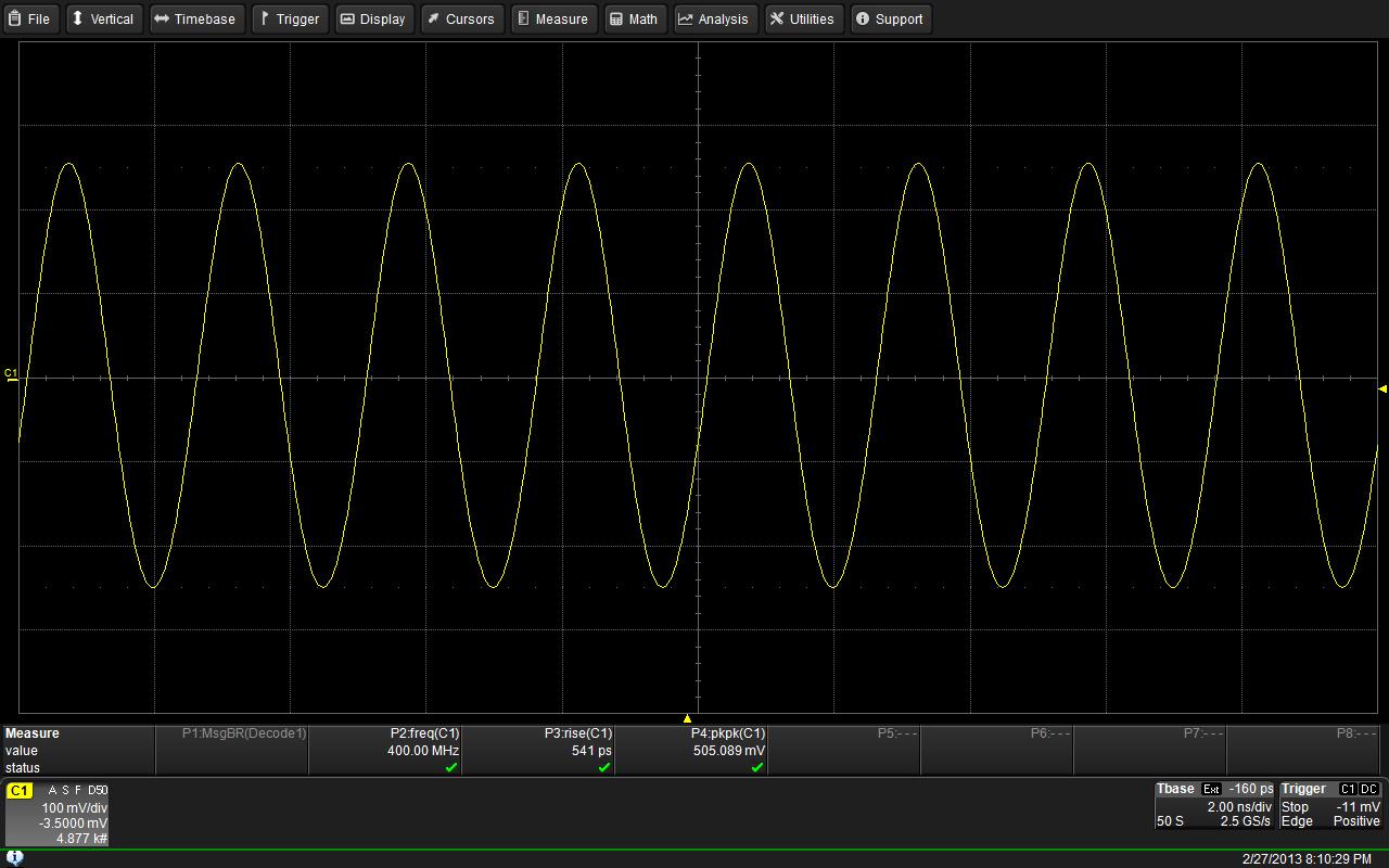
400 MHz sine wave output of a PLL synthesizer
In other words, the scope adapts. That works pretty well within certain limitations. It becomes a problem when there are two signals with large differences in amplitude present at the same time. The ADC has no problem digitizing a sine wave ranging from 0 Volts to 5.12 volts. The same way it has no problem doing the same with a sine wave ranging from 0 – 51.2 mV – the VGA will take care of it, but both at the same time causes trouble. If you think about it for a minute, this will become apparent for you.
Assume the 0 – 51.2 mV signal is noise riding on your wanted signal, the sine wave with 0 – 5.12 volts range. The ADC has to sample over its entire range in order to capture the entire 0 – 5.12 V signal. There’s nothing the VGA can do to lift the 0 – 51.2 signal in a better zone for the ADC. With the proportions being as given, the noise will barely cover more than 3 quantization steps over the whole range. In an real world application, you probably wouldn’t be able to notice anything unusual and miss the noise altogether.
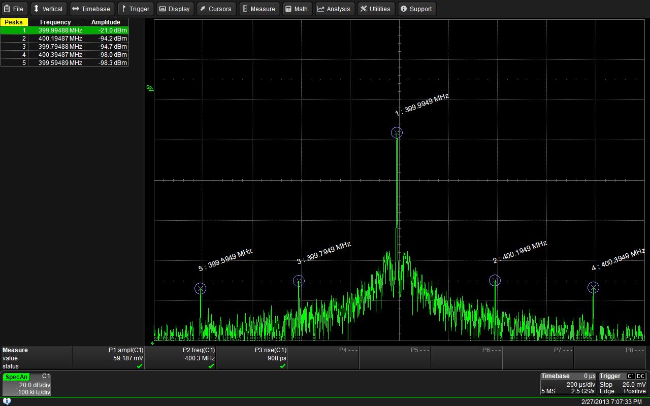
Output spectrum of a 400 MHz PLL with a 200 kHz PFD frequency. Clearly visible, the spurs 200 kHz left and right from the carrier
Dynamic range is a measure for the highest and lowest level that can be detected at the same time. This number directly correlates with the resolution of the ADC. Therefore, some noise or unwanted parts of a signal can be missed with an 8-bit oscilloscope but are clearly visible with a 12-bit oscilloscope.
This entire 12-bit thing isn’t new at all, though. Agilent has 12-bit scopes and Teledyne LeCroy had some for a while, as well. A 12-bit ADC alone won’t do you any good, though. Because we can see signals so much clearer, there are now very stringent requirement to be met in regards of the oscilloscope’s front-end. The VGA needs to be super low-noise and the entire input stage needs to be even more linear than in an 8-bit scope. And that is something that LeCroy claims to have perfected in their HDO series.
Okay, that is all I am going to cover about this subject for now. It is a pretty large subject, though, and one could write books about it. As a matter of fact, I am sure someone has written books about it. As a matter of fact, this article is an extreme reduction of a rather complex matter.
Pictures are always better than words. Therefore, I will write another article on this matter. I will then add noise to a desired signal and show screenshots of an 8-bit scope and then on the HDO (12-bit) for comparison. There’s a lot of talk on the web on why 12-bit is really not worth it and such, but I will not engage in that discussion and let the pictures speak. So stay tuned!
Westerhold, S. (2013), "12-bit vs. 8-bit - What's the difference?". Baltic Lab High Frequency Projects Blog. ISSN (Online): 2751-8140., https://baltic-lab.com/2013/03/12-bit-vs-8-bit-whats-the-difference/, (accessed: June 17, 2026).

- Conducted Emissions on the Bench: Implementing the CISPR 25 Voltage Method - December 15, 2025
- WebP-Images without Plugin - January 14, 2025
- Firewall Rules with (dynamic) DNS Hostname - January 14, 2025