Matching a transistor amplifier’s low output impedance with the higher impedance of an antenna (typically 50 or 75 Ohms) is just one everyday example of where an L-Network can be used. For this article, we are going to design an L-Network that matches a 75 Ohm source (function generator) with a 1 kΩ load (resistor).
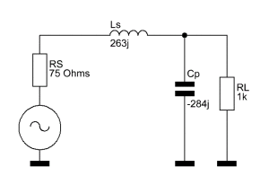
To make it easier for you to understand how this network works, I will present the complete circuit first, explain how it works and then explain how the values are being calculated. Here is the finished L-Network:
RS = Source Resistance (75 Ohms)
RL = Load Resistance
Ls = Series inductance (j263)
Cp = Parallel Capacitance (-j284)
Don’t be frightened by the little “j” in front of the values, in case you have never seen it. The letter “j” in electronics engineering stands for the imaginary unit. Adding “j” to a reactance is basically the so-called “vector notation.” A positive value indicates an inductive reactance and a negative value is always a capacitive reactance. If you are not used to it, you can just think of Ls as an inductor with a reactance of 263 Ohms and of Cp as a capacitor with a reactance of 284 Ohms.
Note that the reactance of a capacitor and an inductor is frequency dependent. Therefore, this circuit does not work well over a large bandwidth.
This circuit makes the 1000 Ohms load ‘look’ like a 75 Ohms load to the source. But how does it work? To answer this question, we have to look at the equivalent circuit. For that, we will reduce the overall circuit to simpler elements, step by step.
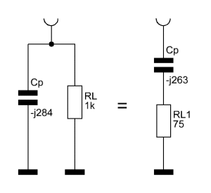
Let’s start with Cp and RL. They are in parallel. The overall impedance of two resistors is calculated as follows:
![]()
Likewise, the resulting complex impedance of a resistor and a capacitor can be calculated as follows:
![]()
In our case, we get:
![]()
75 is the real part in Ohms and -j263 is a capacitive reactance of 263 Ohms. That means the capacitor and resistor in parallel will act like a resistor with 75 Ohms and a capacitor with 263 Ohms reactance in series.
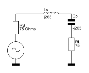
Now if you insert that back into the original circuit and have a close look at it, you may notice something. Look at the reactance of Cp and Ls.
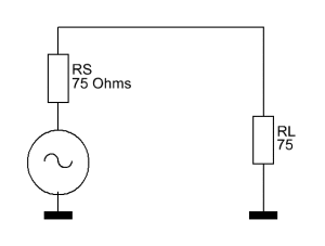
Correct, the reactance of both the capacitor and the inductor are the same, just with different vectors. If you have never worked with a complex impedance beforehand, you will now be amazed by how much easier it makes things. We can simply add the reactances together, and since 263 + -263 is zero, we only have the 75 Ohms load resistance left. Yes, it’s that simple, the source ‘sees’ the 1 kΩ load as a 75 Ω load.
An often-welcomed side effect is that this L-Network acts as a low-pass filter. So, if it’s used to match a low transistor amplifier impedance directly to the higher antenna impedance, one suppresses harmonics at the same time.
If one wishes to have a high-pass characteristic, one can simply switch the positions of the inductor and the capacitor. It really changes nothing. The impedance values, of course, need to be properly adjusted in that case.
Let’s talk about how to design a circuit like this from scratch. We will use the above values, source impedance of 75 Ohms and load impedance of 1000 Ohms at a frequency of 16 MHz. The frequency doesn’t matter until the end when we have to pick actual values for Ls and Cp.
The first thing we have to calculate is the quality factor, or Q factor. It describes how under-damped an oscillator or resonator is, or equivalently, characterizes a resonator’s bandwidth relative to its center frequency. The Q of an L-Network is calculated as follow:
![]()
RLoad = Load Resistance
RSource = Source Resistance
With our values plugged into the equation, we get the following:
![]()
So 3.512 is our Q. The rest is just as simple. To get the needed impedance of the inductor, we use the following formula:
![]()
That means the inductor needs to have an impedance of 263 Ohms at the desired frequency. We can write this as j263 to make sure it’s apparent that it is an inductive reactance. The impedance of the capacitor needs to be the load resistance divided by the Q factor.
![]()
Again, this means that the impedance of the capacitor at the desired frequency needs to be 284 Ohms. Using the vector notation, we write -j284 to indicate that it is a capacitive impedance.
Okay, now we need to find actual values for the inductor and the capacitor. To be able to calculate either one, we need to settle on an operating frequency. For this article we will use 16 MHz. Using the following formulas, we can find the actual values for the parts at the desired frequency:
![]()
That means our inductor needs to have a value of 2.6 μH. I chose a value of 2.2 μH as it is a common value I had in stock. Since the circuitry itself in real life usually contains what’s called parasitic inductance, it won’t throw the circuit off by far. Next up is the capacitor:
![]()
Instead of 35 pF, I used a 33 pF capacitor. Not only is it a more common value, we can again assume a little bit of stray capacitance by the remaining circuit.
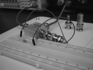
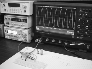
I used a return loss bridge, a signal generator and an oscilloscope to verify the performance of this circuit. And sure enough, it acts just like a 75 Ohm resistive terminator at about 16 MHz. The exact frequency for best operation turned out to be roughly 16.1 MHz.
Update (04/06/2013): I previously wrote that one can not match a high impedance source to a low impedance load. That is incorrect. Naturally, it works perfectly fine the other way around. One only has to switch the position of the load and the source.
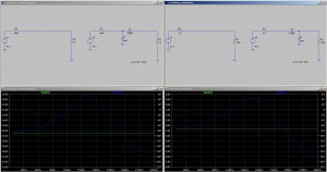
KJ6QBA took out the time to simulate this circuit using LTspice. He also simulated the same circuit used in reverse to match a 1000 Ohm source to a 75 Ohm load. Here’s the result:
Westerhold, S. (2013), "L-Network impedance matching". Baltic Lab High Frequency Projects Blog. ISSN (Online): 2751-8140., https://baltic-lab.com/2013/04/l-network-impedance-matching/, (accessed: January 13, 2026).
- Conducted Emissions on the Bench: Implementing the CISPR 25 Voltage Method - December 15, 2025
- WebP-Images without Plugin - January 14, 2025
- Firewall Rules with (dynamic) DNS Hostname - January 14, 2025
openmakersdaily
Would have been nicer without the lecroy ad in the last image, but that’s very cool anyways. The description is very clear, thanks, I learnt something today.
KF5OBS
No ad in there. The reason I mention the scope the way I do is SEO. Other than that, I think it’s a great scope and it deserves to be mentioned.
erasmus42
“The only problem with this circuit is that it only matches a low source impedance to a higher impedance.”
The key is the element closest to the load. If it is a shunt element, it can reduce the load impedance `seen` at the source. If it is a series element, it `increases` the load impedance `seen`.
KF5OBS
Yes, that’s correct. I should change the article to clarify that this particular configuration only works as ‘step-up’ impedance converter. Then again, I might as well explain that the same in ‘reverse’ works as ‘step-down’. In either case, thanks for the comment. I got tempted into writing it the way I did without thinking as one rarely sees L-Networks as step down, mostly pi-Networks are used. Good catch, thanks!
David
Nicely done. So how about now do the step up version with a Pi network, and show how it looks on the Smith chart? That would be very instructive.
KF5OBS
Working on that. Before I start posting smith charts on my blog I’ll actually write an article on how to read a smith chart. My intend is to not post challenging information that isn’t explained anywhere else in my blog.
Jacob
Your website is wonderful, thanks for this post in particular. I, too, am a fan of clearly written explanations. So in that spirit, can you explain where the Q factor of the L-network came from? Why is it equal to the square root of ([the ratio of the load resistance to the source resistance] – 1)? Thanks and looking forward to more great stuff from you!
Steve
Would you mind breaking down the algebra on:
((-j284*1000)/(-j284+1000))?
It’s been many years for me
Thanks either way,
Steve
KF5OBS #3: L-Network Impedance Matching: | KF5OBS /IP
[…] L-Network impedance matching […]
Viesturs
Thank you very much! I learned a lot from this. Please keep them coming!
Kadhir Sasunoo
I am clear with this 🙂 thank you 🙂 it would be nice if you could help us with T and pi network 🙂
Ravi Durbha
Can U explain how to build a wide band matching network.
Bruce
Excelent. Please continue.
KJ6EJO
This could very nicely be followed by an RF amplifier with impedance matching characteristics…Would love to see a complete tutorial on RF amplifier design, since the youtube seems to be lacking any clear explanations. Great tutorial by the way. I’m doing an RF amplifier design for 150 MHz and I was trying to scale the 7 MHz design I saw in ‘Experimental Methods in RF design’. This gave me an excellent foundation to build from. Keep going! Thanks…
isahatipoglu
Thanks a lot. This is way clear than what I learn in the class:)
Mike Guipo
((-j284*1000)/(-j284+1000))? how to manualyy break this one. thanks
embedded
Hi, did you found the answer? I don’t get it.
Jan
Have a look here ( http://tutorial.math.lamar.edu/Extras/ComplexPrimer/Arithmetic.aspx ) to learn more about complex number arithmetic. Its actually pretty easy.
Kurt
I believe this example is wrong:
Z = ((-j284*1000)/(-j284+1000))
lets first multiply -j284*1000: this is (0-j284)*(1000+j0) = 0-j284000
now the addition -j284+1000: this is simply 1000-j284
now lets divide these results: (0-j284000)/(1000-j284) and this
is: 0 + j1000
so what about the 75-j263 is the example above ?
KF5OBS
Please read up on how to use complex numbers…
Steve
Welcome back!
Steve
I was able to get the math to work after watching some tutorials on YouTube. Search for imaginary number math basics 101
cedrick
How do you calculate the output power?
Ken
Hello KF5OBS: I loved your tutorial and video. However I am a little confused on the math. The eq. is Xc*R which my calcultator say is (284*1000 = 284000) then divided by (284 + 1000 = 1284). This would then give me (284000/1284 =221.8). Not 263 which you came up with.
The in the next step you say: (Correct, the reactance of both the capacitor and the inductor are the same ) , which to me is actually would come out Ls=263 and Cp=221. I am confused what am I looking at wrong. Thank you for your help. Would very much like to know what I did wrong. Thanks Ken AC2QZ.
WH
In the simulation by KJ6QBA, shouldn’t the gain for the blue curves at 16.1MHz be the same for both plots? If Rs and RL are equal in both simulation cases, shouldn’t it simply cut the voltage in half? In the first simulation it is at -19dB and the second one is 5dB.
Alex
Is it possible to do a L matching network with a High-Pass filter?. This one calculation is used in RF antennas matching network?.
Regards.
Pravin Pawale
Will you please calculate the L & C values for Rsource= 200Ohm and Rload= 50Ohm. I am finding it out difficult, please answer it