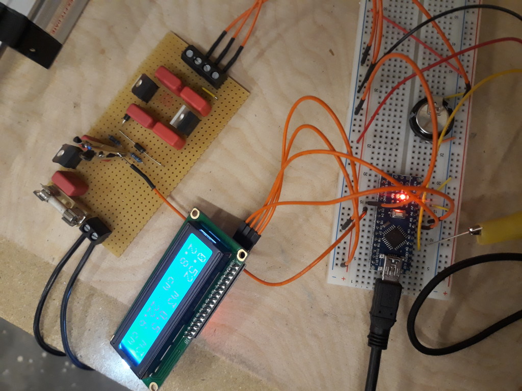
First I should mention that this approach of course also works for other type of storage devices, such an external SD-Card. The simple solution I used in this 12V application is a 2-stage voltage regulator set-up and a power-sense input tied to an interrupt. The first stage gets the input voltage down to 9V. A voltage devider on the 9V rail supplies a steady high signal to PIN 3 of the Arduino Nano as long as a power source is connected to the circuit. As soon as this sense-input falls low, an Interrupt Service Routine (ISR) is triggered that stores the variable to a pre-defined adress of the EEPROM. The second stage consists out of two 7805 type voltage regulators. One for the Arduino Nano and one for all periphial devices such as the LC-Display. The Arduino`s 5 Volt supply voltage is tied to a 1F supercapacitor. This guarantees that the Arduino has enough power available to safely detect the missing supply voltage on the 9V rail and store the example variable to the EEPROM.
The whole Setup looks something like this:
#include <EEPROM.h>

// Some Variable
int SomeVariable;
// Pin to be used as power-down sense
int PWR_DWN_PIN = 3;
// The EEPROM address to be used
int EE_ADDR = 10;

void setup() {
  // Retrieve last stored value of SomeVariable from EEPROM
  EEPROM.get(EE_ADDR, SomeVariable);
  // Set-up Interrupt Service Routine
  attachInterrupt(digitalPinToInterrupt(PWR_DWN_PIN), PWR_DWN_ISR,FALLING);
}

void loop() {
  // Do something cool
  }

// This Interrupt Service Routine will get called on power-down
void PWR_DWN_ISR () {
    // Push SomeVariable to the EEPROM
    EEPROM.put(EE_ADDR, SomeVariable);

}
This Setup works very well. How long the supercapacitor can power the Arduino and whether or not you even need a separate supply rail for periphials depends on the current demand of your circuit. So here`s some math.
The charge of a capacitor is defined as follows:
![]()
Q = charge of capacitor in Coulomb
I = Current in Amps
t = time in Seconds
So if we re-arrange the equation we could wrongly assume that if we divide Q by the current demand of our device, we will get the expected runtime in seconds. But we need to take into consideration that the Arduino does not work all the way down to 0 Volts. We need to define a lower voltage limit and divide the change of charge by the current draw of your device. But how do we get Q to begin with? The charge of a capacitor Q can also be expressed by the following Formula:
![]()
C = Capacitance in Farads
V = Voltage in Volts
So we can combine the two formulas in a way that we can calculate the time (t) if we know the capacitance of the supercapacitor, the expected current draw of the device and the maximum permissible change in voltage.
![]()
So for my example I am allowing the 5 Volts to drop to 4 Volts, I am assuming 100 mA max. current and the supercap has a capacity of exactly 1F.
![]()
10 seconds should be plenty of time to store a variable (or a few more) to the EEPROM. This approach works very well so far. A possible improvement, if needed, migth be to implement a change interrupt trigger instead of a falling edge trigger and re-initialize periphials on power-up if needed (e.g. LCD). This becomes necessary if power is reconnected during a time where the Arduino is still running but periphials where already shut-down. In that case they need a clean initialization before they will function properly.
Westerhold, S. (2018), "Arduino |Automatically Save Variables to EEPROM on Power-Down". Baltic Lab High Frequency Projects Blog. ISSN (Online): 2751-8140., https://baltic-lab.com/2018/12/arduino-automatically-save-variables-to-eeprom-on-power-down/, (accessed: February 13, 2026).
- Conducted Emissions on the Bench: Implementing the CISPR 25 Voltage Method - December 15, 2025
- WebP-Images without Plugin - January 14, 2025
- Firewall Rules with (dynamic) DNS Hostname - January 14, 2025
