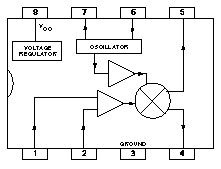
The NE602 and its variants like the NE 612, SA602, and SA612 have been around longer than I have. They make excellent mixers and are used in thousands of amateur radio designs as IF mixer, DSB / SSB modulators, product detectors, and even as plain oscillators.
One thing that seems to be fairly unknown about this Gilbert cell mixer is that the Gilbert cell was initially not designed and patented as a mixer. The Gilbert cell was originally patented as a standard exclusive OR gate (XOR). The use as four-quadrant multiplier was discovered and implemented in practical designs much later.
In fact, the NE602 and its derivatives act just like an XOR if they are slightly overdriven. Thanks to the amplifiers that are built into the NE602, only very little drive level is needed to accomplish the overdrive.
Using an XOR gate in a FM demodulation circuit is nothing new. A XOR gate configured to act as a phase detector and a phase shift network is all that is needed to get an FM demodulator type that is referred to as a quadrature demodulator.
In a nutshell, what happens is that the phase shift network creates a defined 90 degree phase shift between the two mixer inputs at the desired IF frequency. If two signals with 90 degree phase shift but same frequency are applied to the inputs of an XOR gate, the output will result in a 50% duty cycle rectangular signal with twice the input frequency. 50% duty cycle means the output is ‘on’ (represents logic 1) half the time and ‘off’ (represents logic 0) the other half of the time. If any signal with 50% duty cycle is passed through a low pass filter, the output will be the arithmetic middle (average) of the minimum (logic 0 state) and maximum (logic 1 state) voltage of the input signal. A TTL (0 = 0 V, 1 = 5 V) signal with 100 KHz clock rate and 50% duty cycle would turn into a constant 2.5 Volt DC signal after integration through a low pass filter. The DC voltage decreases as the phase difference increases and increases as the phase difference decreases. I will write another in-depth article on how quadrature demodulators work because I want to limit this article to the simple NE602 FM demodulator. UPDATE: How it works: Quadrature detector
Since the exact phase shift is frequency dependent and the DC voltage on the output of the XOR gate (our NE602) is dependent on the phase shift, this behavior makes a perfect FM demodulator.
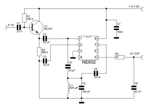
The demodulator works well with frequencies between about 420 KHz to 500 KHz. The required input level is between 0.5 Volts peak-to-peak and 2 Volts peak-to-peak. T1 in conjunction with R2 is an emitter follower amplifier boosting the input signal before handing it off to the input of the NE602 through C2. Instead of a BC547 any other NPN type small signal transistor, such as the 2N3904, will work fine in this circuit.
A tiny amount of the IF signal is branched off through C4 into the LC tank circuit consisting of L1 and C5. C6 brings the now phase shifted signal into the second input of the NE602. The low pass filter consisting of R3 and C8 is filtering out the recovered modulation signal.
The sensitivity of this simple demodulator is about 13 mV/kHz. That’s more than enough even for narrowband FM signals.
Westerhold, S. (2012), "No Tune NE602 / NE612 FM Demodulator". Baltic Lab High Frequency Projects Blog. ISSN (Online): 2751-8140., https://baltic-lab.com/2012/08/no-tune-ne602-ne612-fm-demodulator/, (accessed: January 10, 2026).
- Conducted Emissions on the Bench: Implementing the CISPR 25 Voltage Method - December 15, 2025
- WebP-Images without Plugin - January 14, 2025
- Firewall Rules with (dynamic) DNS Hostname - January 14, 2025


Exclusive OR (XOR) gate phase detector | KF5OBS /IP
[…] No Tune NE602 / NE612 FM Demodulator […]
How it works: Quadrature detector | KF5OBS /IP
[…] No Tune NE602 / NE612 FM Demodulator […]
Ricardo - CT2GQV
Hello,
Nice article, but two questions come to my mind:
Regarding the circuit with the NE602 do you think it could scale to 8-10.7Mhz range of input frequencies, scaling L1/C5 tank to the appropriate frequency?
L1 being 820u and C5 100pF wouldn’t the tank frequency be around 555Khz?
73 de Ricardo, CT2GQV
KF5OBS
Ricardo, thank you for your comment. First off, yes, I believe it would work for 10.7 MHz. You can use a 10.7 MHz “IF can”-type IF tank for L1 / C5. Maybe harvest one out of an old radio. And yes, the mathematical resonance frequency would come out to about 555 kHz. However, as Einstein already noted, as far as the laws of mathematics refer to reality, they are not certain, and as far as they are certain, they do not refer to reality. This is not math’s fault though. We assume our inductors and capacitors to be ideal. A real world inductor, however, has stray capacitance and a real world capacitor has stray inductance. Therefore, the expected resonance frequency is always lower in reality.
Ricardo - CT2GQV
Hello,
I was also thinking in component imperfection. We hams, as Einstein, know that math only match reality to a certain degree.
I will have a go with the circuit at 8Mhz, just have to find a suitable coil in the recycle bin.
Thank you for your time,
73 de Ricardo, CT2GQV
KF5OBS
You can use a standard 10.7 MHz tank out of an old radio and add an extra capacitor in parallel to bring the resonance frequency down to 8 MHz.
bob
Could the Inductor L1 & C5 be replaced with a standard 455khz can coil with internal cap?
KF5OBS
Absolutely! I decided to go with off-the-shelf inductors and capacitors as those 455 kHz IF cans are hard to come by in some areas of the world (Europe for instance). In the US, Mouser usually has some in stock and the guy from http://kitsandparts.com/inductors.php has some as well.
Erik dos Santos
Hi,
Nice Article.
I’m working on a Analog TV Sattelite demodulation and discovered that the audio from sattelite is modulated on a 5,8Mhz Carrier, it’s possible to adapt this circuit with NE602 to work with 5,8Mhz ??
KF5OBS
Yes, absolutely. L1 and C5 would have to be resonant right around 5.8 MHz for that purpose. Or you could use another NE602 type mixer to mix the 5.8 MHz signal down to the 455 kHz or 500 kHz would suffice, too. The exact frequency is not too critical with this circuit.
Geza Faludi
The oscillator input of NE612 is on pin 6 (the base of the transistor), however on your drawing the pahse-shifted signal is fed to the emitter (pin 7). Is there any particular reason of this or is it just a drawing mistake?
KF5OBS
You are correct, it’s a drawing mistake! I’m aware of it but somehow forgot to change the drawing. Now if I could only find the schematic file… Ah well, stay tuned!
Peter
A tiny amount of the IF signal is branched off through C4 into the LC tank circuit consisting of L1 and C5. C6 brings the now phase shifted signal into the second input of the NE602. FROM THIS INFO I AM CONCERNED THAT THAT SECOND INPUT OF THE IC (PIN 2) IS ONLY CONNECTED TO GROUND VIA A DECOUPLING CAP? SO HOW DOES IT FEEDBACK?
N0ZGO
I’m concerned that your caps lock key might have gotten stuck halfway through your comment. 🙂