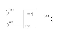
I promised in a previous blog article titled ‘No Tune NE602 / NE612 FM Demodulator’ that I would explain how a quadrature FM demodulator works in another detailed article. The article briefly mentioned how the Gilbert cell mixer NE602 is being ‘abused’ as a XOR gate which is being used as phase detector. Let’s have a closer look at exclusive OR based phase detectors.
The output of an exclusive OR gate is only high (1) when the first OR the other input two is high (1). If both inputs have the same logical state, either high (1) or low (0), the output of an XOR gate is low (0). This can be simplified in saying that the output of an exclusive OR gate is low (0) if the input states are the same. If the input states are different, the output will be high (1).
If one applies a rectangular signal with exact same parameters, such as frequency and amplitude, to an XOR gate, the output of the XOR gate will be a logical 0 if the phase difference between the two signals is 0°. This is because the two signals have the exact same logical state at any given point in time.
The opposite happens if the signals have a phase difference of 180°. Remember, 180° phase difference means that the second signal is a perfect mirror of the first signal. With 180° phase difference the second signal will be at a logic low (0) state if the first signal is high (1) and vice versa. Because the signals have exactly opposite logical states at any given point in time, the output of the XOR gate will constantly be high (1).
For this experiment I am using a HEF4030 with a supply voltage of 10 Volts.
0° and 180° are the two extreme values of an XOR gate based phase detector. An XOR gate based phase detector interprets phase differences greater than 180° as actual phase difference minus 180°. For instance, a phase difference of 270° will be interpreted as 90°. This is because an XOR gate based phase detector doesn’t know which of the two signal was ‘first’ and which signal is preceding which.
Alright, now we took a look at the two extreme values. So far it’s easy to follow. But what happens if the phase difference is somewhere between 0° and 180°? Well, let’s try it out, shall we?
Let’s hook up two rectangular signals with the same amplitude and frequency but 90° phase difference to the input of the XOR gate. I captured the in- and output signals with a logic analyzer. Here’s the result:
The output shows a signal with 50 % duty cycle and twice the frequency of the input signals. A duty cycle is the time (in percent of the total time) a signal spends in the logical high (1) state. The average voltage of any signal with 50 % duty cycle is half its peak-to-peak voltage, because the signal is half of the time low (0) and half the time high (1).
If the phase difference of the input signals decreases, the duty cycle also decreases. Therefore, the average voltage of the output signal also decreases. If the phase difference increases on the other hand, the duty cycle increases. Therefore, the average voltage increases. One could also say that the width of the positive pulse of the output signal changes proportionally to the phase difference of the input signal. Because this is the case, the output signal is called to be pulse-width modulated (PWM).
We can simplify the behavior by saying that the average output voltage is directly proportional to the phase difference of the input signal if the phase difference is between 0° and 180°.
We can write out a formula describing this behavior like this:
Vout = (Vdd / 180) * ΔΦ
Vout = Average output voltage
Vdd = Supply voltage of the XOR gate
ΔΦ = Phase difference in degrees (°)
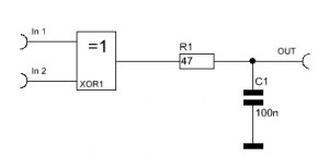
If we want to extract only the average voltage and reject the rectangular signal, we can do that with a simple RC low pass filter.
If the output of the XOR gate is high (1), C1 is being charged through R1. If the output of the XOR gate is low (0), C1 is being discharged over R1. Since this happens extremely fast, the voltage over C1 will essentially appear to be the average of the gates output signal. Mathematically this process is called integrating. Therefore a low pass filter is also referred to as an integrator. A high pass filter would be called an differentiator.
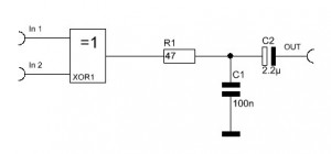
If one only cares about the relative change is phase difference, for instance in an PM demodulator circuit, one can add another capacitor to extract only the change in the voltage ( which is proportional to change in phase difference).
This circuit is capable of recovering audio (or data) from a phase modulated signal. To test this circuit one could use a signal generator to apply a signal of constant amplitude, frequency and phase to input one. If then a phase modulated signal of same frequency and amplitude is applied to input 2, the recovered audio (or data) will be available from the output of the above circuit.
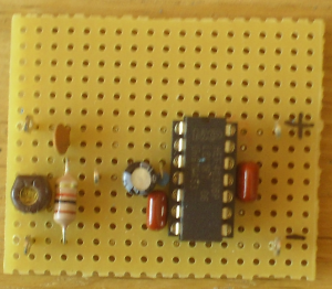
This circuit can easily be assembled even by beginners. I used a little piece of perforated PC Board for this experiment.
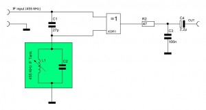
To turn this whole circuit into an FM demodulator one only needs to add a frequency dependent phase shifter. A simple parallel LC tank circuit and a capacitor will serve this purpose well.
For a 455 kHz IF possible values for L1 and C2 could be 820 microhenry (L1) and 100 pF (C2). Mathematically the resonant frequency is much higher than 455 kHz, yet practically it will fit perfectly. This is due to parasitic stray capacitance / inductance in the circuit. Those metal shielded IF filters, often referred to as IF can, would do an excellent job as LC tank circuit as well. They are, however, difficult to come by nowadays.
In case you would like to see what exactly is going on in the phase shifting network, check out my article ‘How it works: Quadrature detector‘.
Westerhold, S. (2012), "Exclusive OR (XOR) gate based phase detector". Baltic Lab High Frequency Projects Blog. ISSN (Online): 2751-8140., https://baltic-lab.com/2012/09/exclusive-or-xor-gate-based-phase-detector/, (accessed: January 16, 2026).
- Conducted Emissions on the Bench: Implementing the CISPR 25 Voltage Method - December 15, 2025
- WebP-Images without Plugin - January 14, 2025
- Firewall Rules with (dynamic) DNS Hostname - January 14, 2025
How it works: Quadrature detector | KF5OBS /IP
[…] Exclusive OR (XOR) gate based phase detector […]
Review: Abracon ABFT Frequency Translators | KF5OBS /IP
[…] the flip flop is then compared to the 10 MHz reference by a simple XOR gate based phase detector. How an XOR gate based phase detector works has been explained in one of my previous […]
quang do
could you explain how do you calculate the value for the filter, i cant find the 100nF and 2.2uF available in my school’s stock room
Heywood Garth
I just wanted to thank you for simplifying this topic into hands on terms. I amm 55 years old and have been an electronic repair bench tech for 38 years. Due to Dyscalculia, it is very difficult for me to comprehend advanced mathematical concepts which has always limited me to a mostly hands on realm. Your practical explanations and actual circuit complements make it easy and fum to memorize and experiment with. Thank you so much for you effort and consideration, it is invaluable to people like myself and greatly appreciated.