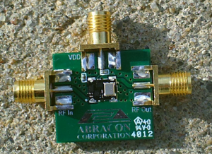
The Abracon ABFT frequency translators / jitter attenuators are available as 20 MHz and 40 MHz versions. They both require a 10 MHz reference frequency input, have an ultra small footprint (5.00 x 7.00 mm) and only consume 14 mA under lock. Abracon sent me an evaluation board for the 20 MHz version. Let’s check it out!
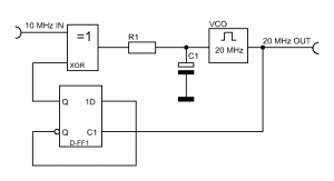
Before we dive in, let’s talk about clock multiplication using a classic PLL design. To talk about the problems associated with classic PLL multiplier circuits, here is a simple 10 MHz to 20 MHz multiplier circuit:
I am intentionally mixing block diagram symbols and actual circuit drawing symbols for clarity. The VCOs output signal is divided by two using a D type flip flop. If the VCO frequency is exactly 20 MHz, the output of the D flip flop is 10 MHz. The output of the flip flop is then compared to the 10 MHz reference by a simple XOR gate based phase detector. How an XOR gate based phase detector works has been explained in one of my previous articles.
A big problem with that circuit (and most PLL designs for that matter) is the following: if the input signal is exactly 10 MHz with absolutely no jitter, everything works well. The phase noise performance of the output would then primarily depend on the used VCO. The problem is, jitter free signals simply don’t exist in the real world. Remember, jitter is the undesired deviation from true periodicity of an assumed periodic signal. Jitter can be observed in several of the signal parameters. Troublesome for this circuit are phase and frequency errors. We will talk about frequency errors only as every phase error forcibly causes instantaneous frequency errors.
Let’s assume the input signal jumps between 9,999,990 Hz and 10,000,010 Hz. Our PLL circuit is now doubling this error because it is a fixed x 2 multiplier. The jitter on the output signal will therefore essentially be twice the jitter on the input frequency. The output frequency will therefore jump between 19,999,980 Hz to 20,000,020 Hz. This condition is quite obviously undesirable.
A possible workaround is to increase the time constant of the loop-filter (R1 + C1). If overdone, the PLL will turn into a Frequency Locked Loop (FLL) and it will no longer be able to react to quick changes in phase and frequency differences. While this reduces the aforementioned problem drastically, the big loop time introduces a new problem. The loop is now too slow to correct errors quickly enough to have a reliable output signal. Additionally, the lock-time is increased significantly. Both are of course undesirable conditions.
Needless to say, designing such a PLL can be a big pain in one’s proverbial behind when there are heightened phase noise / jitter requirements on the table. It’s simply nothing that can be accomplished with your common 4046 CMOS or similar. So instead of trying experiment with different loop filters and trying to find the ‘right’ trade-off of loop properties for hours on end, why not grab something off the shelf that works right away? And that takes us right back on topic of the Abracon ABFT frequency translator.
Here are the tech-specs straight from the datasheet [1]:
- 5x7x2 mm SMT, RoHS Compliant reflow-able package
- +3.3V Supply Voltage
- Temperature Range: -40ºC to +85ºC
- LVCMOS Output
- Frequency Stability Over the Whole Temperature Range: ± 25 ppb
- Supply Current Under Lock: < 14 mA
- Rise Time: < 1.2 ns
- Stand Alone Aging (10 years): + 12 ppm
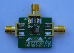
To make the evaluation and experimentation process simpler, Abracon offers a small evaluation board for the ABFT [2]. The board’s dimensions are about 40 x 30 mm. Equipped with 3 industry standard SMA connectors (Reference in, Vdd, and RF Out), the board can quickly be implemented in test setups.
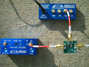
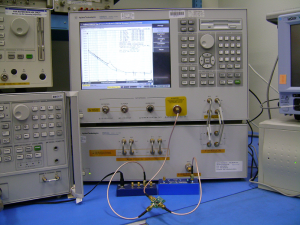
But that’s enough text for now. It’s time to look at some pictures. I used the ABPSM-ULN-A ultra low noise power supply module and the Abracon Sync ‘n Go together with the ABFT eval board in my test setup.
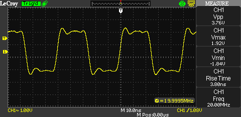
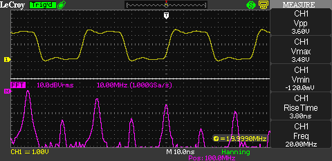
The first thing we’re going to have a look at is the output waveform. I am using the LeCroy WaveAce 1002 for the following two screenshots.
Shape, voltage and frequency look good. There’s a bit of ringing due to an impedance mismatch between the probe and the ABFT. The overshoot is caused by the impedance mismatch, as well. You might note that the rise time measured by the WaveAce is higher than what the ABFT’s datasheet claims. But no need to worry — what’s displayed here is the rise time of the LeCroy WaveAce 1002 as shown in my review. I simply do not have a scope that is capable of dealing with 1.2 ns rise time.
No surprise in the frequency domain either. Because an ideal rectangular signal is made up of sine waves of the fundamental frequency and uneven multiples of the fundamental frequency, the uneven harmonics displayed on the WaveAce 1002 are stronger than the even ones.
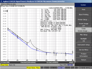
Now it’s time to look closer at the phase noise performance. Signal source analyzers are extremely expensive. That’s why I do not have one available to me. However, Abracon’s Syed Raza (Director of Engineering, Abracon Corporation) supplied proof for the phase noise performance without hesitation. He is also using the ABPSM-ULN-A ultra low noise power supply module and the Abracon Sync ‘n Go together with the ABFT eval board in his setup. The output of the ABFT eval board is fed into an Agilent E5052A signal source analyzer.
The phase noise performance measured by the E5052A is at any given marker point better than what is mentioned in the datasheet. The black line is the phase noise of the ABFT and the blue line is a 10 MHz Stratum III reference.
The datasheet has some additional phase performance screenshots. Abracon shows for instance what happens when the input of the ABFT is fed with a dirty crystal oscillator. The phase noise is significantly improved.
Abracon suggests that the device is suitable for use in Telecom applications such as base station equipment, broadband modems, DSLAMs and base stations.
I can think of much simpler applications than that. For instance, 20 MHz and 40 MHz are both common clock frequencies for microcontroller. If a high precision requirement or simply the need to synchronize the MCU application to an external 10 MHz reference arises, this is pretty much the simplest way to go.
It is noteworthy that the ABFT still puts out a valid signal in free running mode if no reference input signal is present. Therefore, the ABFT would be very suitable for applications where a free-running mode is desired as well as the option to sync the device to a more accurate 10 MHz reference signal when required. I personally can see myself using this feature in future microwave synthesizer designs.
Mouser has both the 20 MHz and the 40 MHz versions in stock for ![Rendered by QuickLaTeX.com 26.30 per piece [<a href='http://www.mouser.com/ProductDetail/ABRACON/ABFT-20000MHz-T2/?qs=sGAEpiMZZMtXsj1ZQc4vOdouKcUyt1vCyotnYbZlcy0%3d' target='_blank'>3</a>]. That price is for single quantities. The price drops to](https://baltic-lab.com/wp-content/ql-cache/quicklatex.com-fe988c7cc78dff33ca962622f2843c89_l3.png) 21.04 per piece for 500 ABFT modules. Reels are available with 250 or 1000 units per reel.
21.04 per piece for 500 ABFT modules. Reels are available with 250 or 1000 units per reel.
Links and Sources:
[1] Abracon ABFT Datasheet, Abracon: http://www.abracon.com/
[2] Abracon ABFT Evaluation Board, Abracon: http://www.abracon.com/
[3] Abracon ABFT 20 MHz, Mouser Electronics: http://www.mouser.com/
Westerhold, S. (2012), "Review: Abracon ABFT Frequency Translators". Baltic Lab High Frequency Projects Blog. ISSN (Online): 2751-8140., https://baltic-lab.com/2012/11/review-abracon-abft-frequency-translators/, (accessed: January 8, 2026).
- Conducted Emissions on the Bench: Implementing the CISPR 25 Voltage Method - December 15, 2025
- WebP-Images without Plugin - January 14, 2025
- Firewall Rules with (dynamic) DNS Hostname - January 14, 2025
DSSS / BPSK Clock Recovery with Abracon ABFT | KF5OBS /IP
[…] Review: Abracon ABFT Frequency Translators […]