Today, I tried out a 300 Watt 12 V DC to 220 V AC inverter I bought off eBay not too long ago. For just $26.50 including shipping, I got it from the eBay seller hi-autopia [1]. I was already suspicious because of the low price, but decided to give it a try anyway. So here it is:
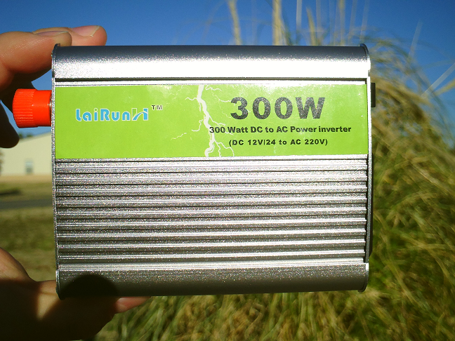
Label of the One-Hung-Low brand 300 W inverter
I could not find any information on this manufacturer at all. A tag on the side of the inverter indicates it was manufactured somewhere in Asia. So how well would this One-Hung-Low brand inverter perform? Well, let’s start with some visible results of my test:
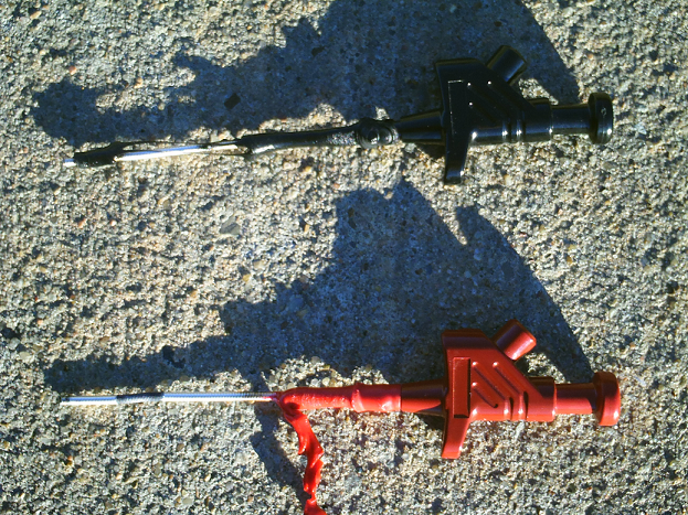
Molten 4mm probes (Hirschmann Kleps 30)
Yes, those were perfect 4mm test clips at some point. So what happened? The inverter was connected to a 12 V battery through the above test clips and a pair of 4mm test leads. Probably not the best for continuous current at the maximum 300 Watts, but okay for the 60 Watts I used as a test load. And just for the record, the DC hook-up wire that was supplied with the inverter was about half as thick as my test leads.
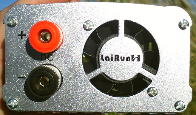
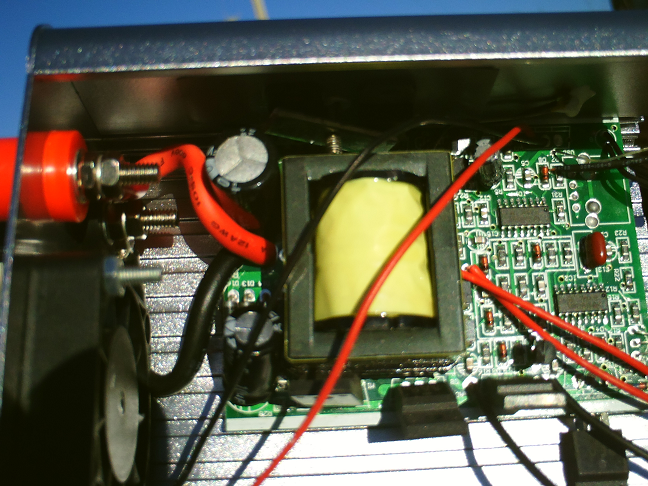
Input side of the 300 W inverter.
The load I used for the test was a 60 W 220 Volt soldering iron. A soldering iron is an entirely resistive load and shouldn’t cause any hardship on an inverter. I measured the output voltage across the output of the inverter, a steep 420 volts while idle. Once I connected the soldering iron, it fell to 230 Volts. The voltage seemed to drop every second or so. It looked as if the circuitry had difficulties regulating the output voltage. But before I could hook up my oscilloscope and take a screenshot, I started smelling smoke. And shortly after that, the smoke started coming out of the case of the inverter. My test clips started glowing bright orange before I finally got to disconnect the inverter from the battery.
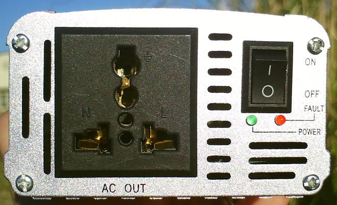
Output side of the 300 W inverter.
I thought this was awfully weird. Not only was the behaviour of the inverter strange, it seemed like the inverter had no protection circuitry whatsoever. While thinking about it, I noticed that this inverter does not have a fuse on the input side like most professional inverter do. So the fuse had to be on the inside. I mean, it couldn’t be that the inverter isn’t fused, right?
Closer look at the input section of the inverter
Well, guess again, there’s no fuse or any other means of protection in the input circuitry. To skip ahead: There’s none in the output section either. But more about that later. Just by glancing at the circuitry, I suspect this is a modified sine wave inverter. And with that in mind, I am very surprised about the size of the transformer (yellow). For 300 W output, I’d expect a transformer to be capable of handling at least 500 VA. The transformer used here looks more like 12 VA…
Close up view of the circuitry revealing several safety issues
The first thing that caught my eye was the lack of a proper routing for the 220 V traces. At high voltages, traces must be spaced out as far as possible to avoid arcing to ground planes or other traces. Ideally, the design should implement an actual physical separation by utilizing milled notches. In the above pictures, the 220 V wires are the two thin black wires in the bottom right corner.
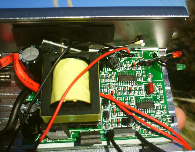
General overview of the 300 W inverter
The low spacing between the PCB and the case is concerning, as well. There are absolutely no precautions taken in order to prevent the solder joints to touch the case. As a matter of fact, the two bend transistors in the bottom left corner may have been bent over the way they are for some degree of “protection.”
There seems to be a temperature sensor as fault prevention. But just by looking at the discolored casing of one of the two driver MOSFETs, I suspect this fault detection is not very effective, to say the least.
By the way, the device is, of course, not certified under Part 15 of the FCC rules.
I did send a message to the eBay seller hi-autopia about this and will supply him with a link to this article. His reaction should be rather interesting. While I doubt he knew about the quality (or the lack thereof), this is a great opportunity for him to show how well he responds to customer complaints and how he resolves them.
Links and Sources:
[1] hi-autopia, eBay: http://www.ebay.com/
Westerhold, S. (2013), "One-Hung-Low brand 12 V to 220 V inverter". Baltic Lab High Frequency Projects Blog. ISSN (Online): 2751-8140., https://baltic-lab.com/2013/01/one-hung-low-brand-12-v-to-220-v-inverter/, (accessed: July 22, 2026).

- Conducted Emissions on the Bench: Implementing the CISPR 25 Voltage Method - December 15, 2025
- WebP-Images without Plugin - January 14, 2025
- Firewall Rules with (dynamic) DNS Hostname - January 14, 2025
openmakersdaily
Well, at least you got a nice profiled aluminium case for a project 😉
Or the description was not right, and you bought a smoke machine 😉
The whole story is just incredible. How can anyone build and/or sell “something” like that?? This is not a crappy hobbyist kit, some kind of test had to take place at a factory where it was assembled, so it’s an intentionnaly bad product!