For some reason, my new BCD996XT scanner wasn’t working as expected on the statewide digital (APCO 25) radio system. Since this radio system is the primary reason why I got this new scanner, I had to come up with a solution. In addition, I really wanted to expand my receive coverage geographically. This article shows how to improve receive signal strength, greatly increase geographical coverage and reduce out-of-band interference.
So where to start? The obvious. Taking a snapshot of the current situation. I am using a wideband discone antenna mounted on my roof. Since this is a very broadband antenna, I imagined that it was catching a whole lot of signals that I didn’t really care about. A look at the MDO4104B-6’s spectrum display confirmed this.
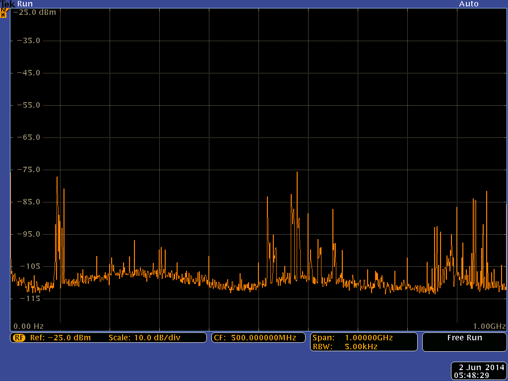
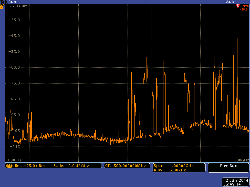
0 MHz – 1 GHz spectrum without preamplifier
The bandwidth is 0 – 1000 MHz (100 MHz / div). Even though the resolution bandwidth is 5 kHz, the MDO4104B-6 was actually pretty fast. But that’s just an aside. You can clearly see the strong broadcast VHF signals on the left. Then there are a lot of signals between 500 and 700 MHz, as well. I have absolutely no interest in signals in that range. And over to the right, you can see — among other things — the desired signals. The control channels for the APCO 25 systems in my area are mostly between 850 and 860 MHz.
Since I am primarily using the BCD996XT scanner for the APCO 25 system, I was willing to filter out anything that’s not in the 800 – 900 MHz range. I realize that I’ll lose the capability to monitor most of the VHF and UHF channels (Aircraft, Amateur Radio, Law Enforcement, Business, etc.) by doing this. But I do have plenty of other analog scanners and I also have 2 more wideband discone antennas laying around. So my decision was made; Optimize the antenna system for 800 – 900 MHz and set up a second scanner (BCT15X) for analog channels.
I also decided to combine the signals of the wideband discone antenna (for local sites) and a commercial 850 MHz Yagi antenna (remote sites).
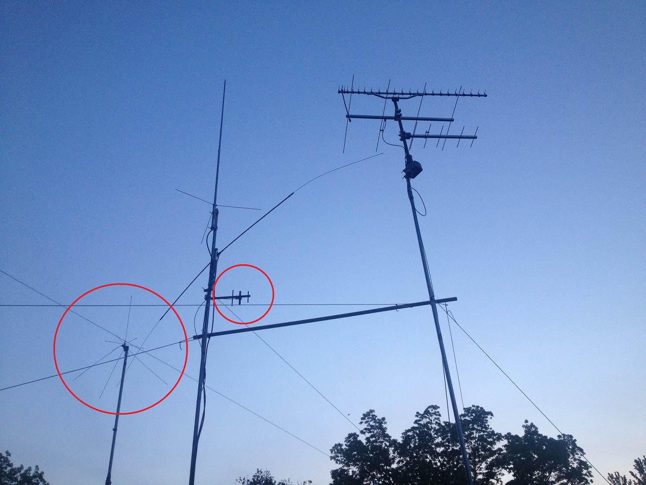
The two scanner antennas in my yard
APCO 25 sites are smart in that they actually know what data it needs to relay and what not. If there is no radio logged into the site with a certain talk group, there is no need for this site to relay activity associated with that talk group. So while the discone picks up local sites very strongly, it may be of absolutely no help for communication of a neighboring county if there are no radios of those agencies being used locally. Looking at the map, I realized that there were about 6 remote sites northeast of my house. Perfect for a commercial 850 Mhz Yagi made by Larsen.
So besides filtering, I now had to combine two signals from the two antennas. And I thought while I was at it, I might as well include a preamplifier. For practical reasons, mostly cable loss compensation, it’s always smart to put the preamplifier close to the antenna. I did have a rugged outdoor case laying around. All I had to do is select the right things to put in it.
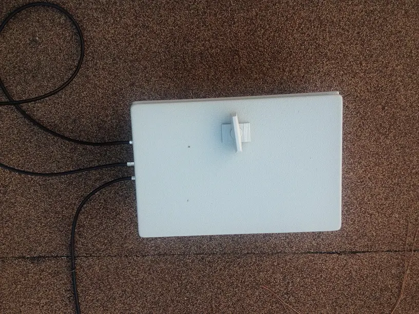
850 MHz Preamp Box
While looking for a combiner, I found one that actually had a bandpass characteristic for 800 – 920 Mhz. It’s the Mini Circuits ZN2PD-920+ [1]. From Mini Circuits are also the 800-1050 MHz SMA inline filter [2] and the amplifier (ZX60-2534M+) [3]. That’s pretty much everything needed except I did not want to run an extra power line for the amplifier. Therefore, I also ordered two Bias-Tees [4].
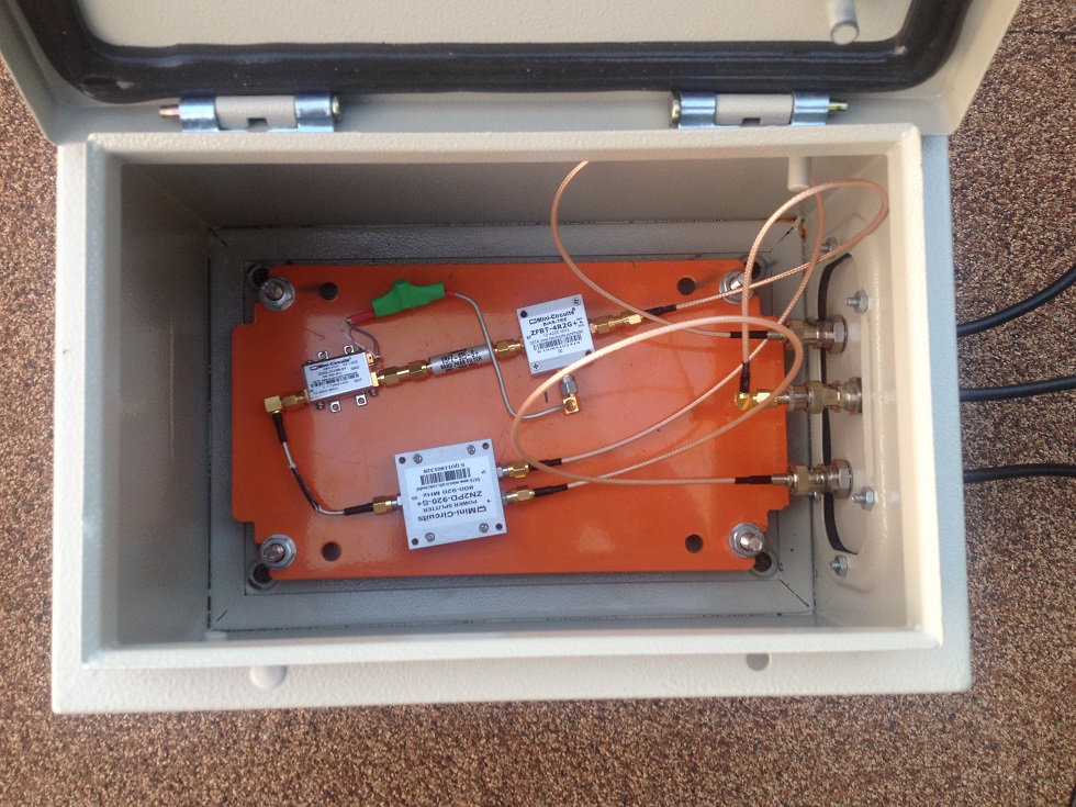
Inside the 850 MHz combiner / preamp / filter box
The wiring is pretty straight forward. The two signals from the antennas are being combined by the combiner, then being amplified by the amplifier and filtered by the bandpass filter. In that order. I was debating to put the bandpass filter in front of the amplifier. After all, amplifiers behave according to the “garbage in, garbage out” principle. Since the combiner had a bandpass characteristic, I did not want to introduce anymore loss.
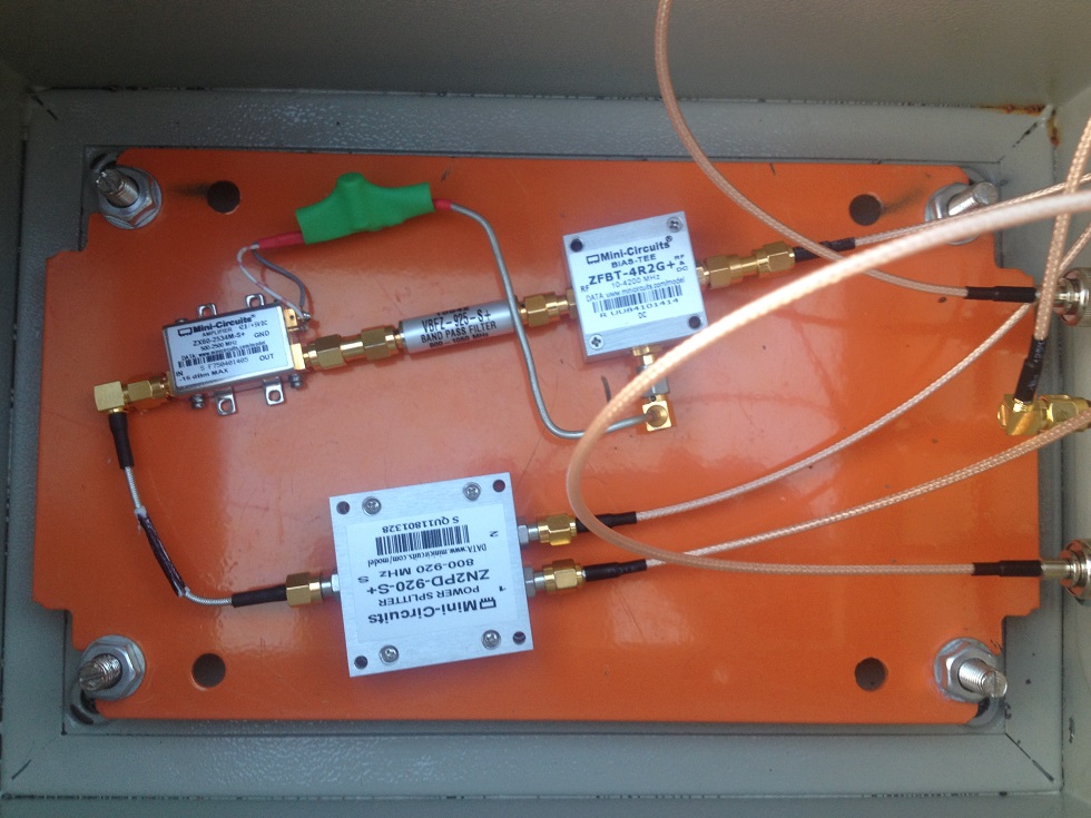
Close-up of the 850 MHz combiner / preamp / filter set-up
I cut a small piece of rigid RF cable in half and soldered two capacitors (100 µF & 100 nF) as well as two wires for the amplifier’s voltage supply on the end. An old power supply for a USB hub supplies the 5 V for the amplifier on the other side of the coax.
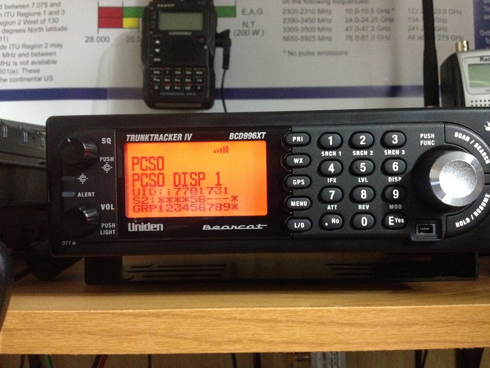
The BCD996Xt scanner is very happy with the signal levels
Immediately after hooking up the scanner, I could tell a great improvement in performance. Not just remote, but also local signals were much clearer and the lock time for the scanner was significantly faster. Beforehand, I often missed the beginning of a transmission. Now I can eavesdrop right from the start. A quick look at the spectrum analyzer confirms that the signal situation increased significantly.
0 MHz – 1 GHz spectrum with preamplifier
In case you’re interested in building a similar setup, here are the links to the datasheets of the Mini Circuits products used.
[1] Mini Circuits: ZN2PD-920+, Power Splitter/Combiner, 800 to 920 MHz: http://www.minicircuits.com/pdfs/ZN2PD-920+.pdf
[2] Mini Circuits: VBFZ-925, BPF, 800-1050 MHz: http://www.minicircuits.com/pdfs/VBFZ-925+.pdf
[3] Mini Circuits: ZX60-2534M, Low-noise amplifier: http://www.minicircuits.com/pdfs/ZX60-2534M.pdf
[4] Mini Circuits: ZFBT-4R2G+, Bias-Tee: http://www.minicircuits.com/pdfs/ZFBT-4R2G+.pdf
Westerhold, S. (2014), "850 MHz Scanner Preamplifier / Filter Project". Baltic Lab High Frequency Projects Blog. ISSN (Online): 2751-8140., https://baltic-lab.com/2014/06/850-mhz-scanner-preamplifier-filter-project/, (accessed: May 6, 2026).

- Conducted Emissions on the Bench: Implementing the CISPR 25 Voltage Method - December 15, 2025
- WebP-Images without Plugin - January 14, 2025
- Firewall Rules with (dynamic) DNS Hostname - January 14, 2025
850 MHz scanner preamplifier / filter project – RLabs
[…] KF5OBS writes: […]
Anton
Are you worried about phasing effects between antennas? Try varying horizontal distance (by few feet) between antennas and observe your RX frequency of interest level on your spectrum analyzer.
KF5OBS
It could quite possibly be a problem, yes. But it doesn’t appear to be a problem in my case. The AWIn sites that I am listening two use different control channels at their different locations. So the huge signal level difference for each site on each antenna probably prevents any adverse phasing effects.
Anton
A quicker test would be to disconnect omni antenna from your combiner while observing a signal from distant site. If it does not change, then there is no adverse phasing effect. I would do it just out of curiosity.
KF5OBS
Obviously I did compare the spectrograms of each antenna individually vs. the combined result. Didn’t notice any adverse effects at all. However, that doesn’t mean that there are none. Especially if we talk abotu phasing, there’s many changing parameters involved. The distant sites are really pretty far away for the discone antenna. So that may be a really convenient factor here.
Haskell Moore
Greetings,
First, thanks for the excellent article and information; I found it quite useful. I’m faced with a similar problem receiving an APCO 25 system that’s about 30 miles from my home, and have tried using a “Telewave, Inc. – 806-960 MHz 20dB Inline Preamplifier”, but without success. This is a very high quality, commercial grade cellular pre-amp, but not sure if it’s fit for purpose for what I’m doing. Is there anything significant about the characteristics of the amp you used as opposed to this one?
Thanks in advance,
Haskell – W5HLM