This article will show how to design a 2-way equal split lumped-element Wilkinson power divider with 50 Ω impedance for 28 MHz. Lots of big words; reread just to make sure you read it correctly and you don’t have to read through this article just to realize it’s not what you need. The Wilkinson works both as splitter and combiner. To make life easier, I’ll only refer to it as “Wilkinson splitter” or just “Wilkinson” in this article. If you prefer watching videos, scroll down to the end of the article for the two videos that I made on this topic.
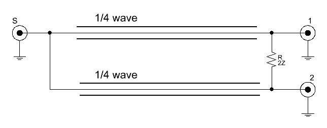
Let’s start by having a look at the classic transmission line version:
There is really not much circuitry involved. A great example how efficient simplicity can be. The trick is that any signal traveling through the resistor to the other port will meet its historical 180° (= 2*1/4 λ = 1/2 λ) mirror and get cancelled. The impedance of the transmission lines needs to be equal to the square root of 2 of your desired input / output impedance (Z0). Let’s use 50 Ω for this design. That is all we need to define for now to calculate the transmission line impedance as follows:
![]()
![]()
In this example, the transmission line impedance needs to be 70.7 Ω. Perfect, the other value we need is the value for the resistor. That value is simply twice Z0.
![]()
![]()
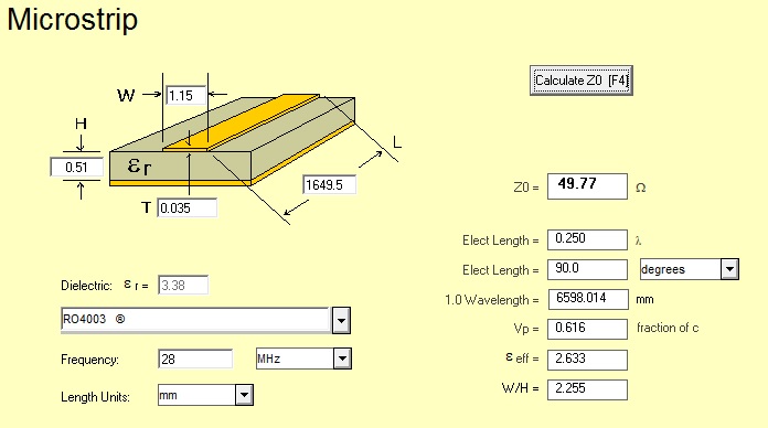
And that is everything we need to calculate for a classic 1/4 λ Wilkinson. Besides the quarter wavelength of course, but I firmly believe that all my readers are capable of doing that. But remember that you need to calculate the electrical quarter wavelength, not the mechanical quarter wavelength. Depending on the velocity factor of the material used, the difference can be significant. Luckily, there’s free software out there that can do the job, like AppCAD from Agilent (or I guess now Keysight Technologies). Here is an example using fairly standard Rogers 4003 PCB material at 28 MHz:
So for a Wilkinson splitter at 28 MHz, we’d need a ~1.65 meter (> 5 feet) transmission line. Say what? Exactly! That’s why it’s not very practical to build a Wilkinson with actual transmission lines at low frequencies. So how do we shrink a transmission line? The writers of “Honey, I Shrunk the Kids!” were unavailable for comment so let’s use pi filters instead. It is possible to calculate a pi network that exhibits similar electrical characteristics as a 1/4 λ transmission line. The main characteristics we care about is the propagation delay and the impedance matching capabilities. The pi network is a great performer in both categories.
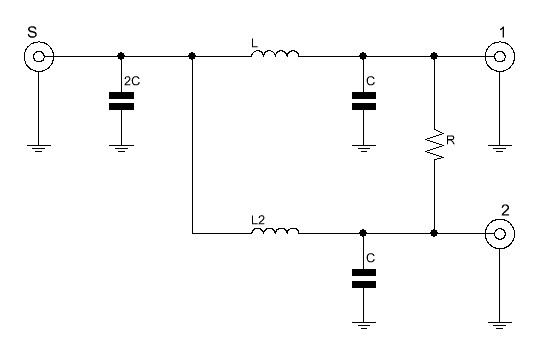
So if we redraw the transmission line Wilkinson into a lumped element equivalent and simplify, we get this:
Same electrical behavior, but more math. In other words, much sexier. The math for the resistor R remains the same. 100 Ω in our example. The first thing to calculate is the inductance of the inductor L. L needs to have the same impedance as the transmission line would need to have. In our example, that was 70.7 Ω. But more generalized, the formula and the result for our example looks like this:
![]()
![]()
That is pretty close to 400 nH, so for simplicity, let’s work with that. Now that we have L, C is very easy to calculate, as follows:
![]()
![]()
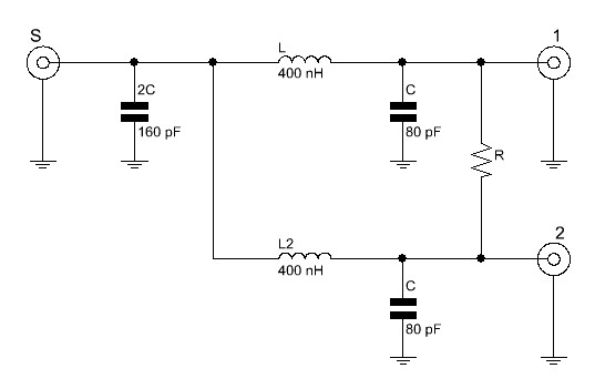
Let’s call 80 pF close enough. Remember that the first capacitor on the sum port has a value of 2C, 160 pF in this case. If we insert all the values we have just calculated into our circuit drawing, we get this:
That’s it. It’s really not that difficult once you have done it at least once. Like most things in life. And the more you design, the better you’re going to get at it. Remember that reality and math sometimes don’t agree with each other. For instance, you are going to find that a lumped-element filter will actually have a lower “ideal” frequency as what it has been calculated for. That makes perfect sense and is because of stray capacitance and stray inductance that is present in any real world circuit. So take care to minimize these parasitic reactances, and if you have to round parts values, try rounding down instead of up.
Our friends over at Microwave 101 also have great articles on the Wilkinson. You can find much more information on special cases like multi-stage Wilkinsons, unequal split Wilkinsons and other fancy things that belong into every RF magician’s bag of tricks. So really, go check them out [1].
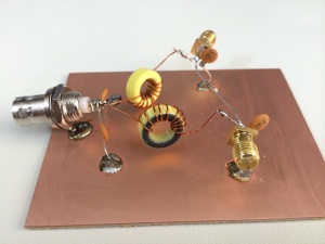
And if you wonder why I keep calling this sort of stuff sexy, I hope this Manhattan style (=ugly construction) build of the 28 MHz Wilkinson we just calculated will answer this question for you:
Videos
If you prefer watching videos, or you just like hearing my voice, check out the following videos. Remember to subscribe to my YouTube channel and like the videos if you did indeed like them.
Links and Sources:
[1] Microwave 101, Wilkinson Power Splitters: http://www.microwaves101.com/
Westerhold, S. (2014), "Lumped-Element Wilkinson Splitter / Combiner Design". Baltic Lab High Frequency Projects Blog. ISSN (Online): 2751-8140., https://baltic-lab.com/2014/09/lumped-element-wilkinson-splitter-combiner-design/, (accessed: January 9, 2026).
- Conducted Emissions on the Bench: Implementing the CISPR 25 Voltage Method - December 15, 2025
- WebP-Images without Plugin - January 14, 2025
- Firewall Rules with (dynamic) DNS Hostname - January 14, 2025
Norte
Hi Master! Im so sorry for my ignorance.. im beginer on the microwaves resarches.. and im loving this. We had a lot of Capcitors and inductors calculations.. but when ‘im developing the patch on CST Studio… i wll not put capacitors or inductors in the project… or not? can i just discover the impedance of the line by my simulations? is it enough?
David
* Lumped Element 2-Way Wilkinson Splitter / Combiner Design:
* Design Parameters:
Zo = 50 Ohms
Fo = 28 MHz
* Fundamental Equations:
R = 2 * Zo
At Fo: XC = XL = Sqrt(2) * Zo = 70.711 Ohms
* Resistance:
R = 2 * Zo = 2 * 50 = 100.000 Ohms
* Inductance:
XL = 2 * Pi * Fo * L = Sqrt(2) * Zo
L = (Sqrt(2) * Zo) / (2 * Pi * Fo)
L = (Sqrt(2) * 50) / (2 * Pi * 28E6) = 401.927 nH
* Capacitance:
Fo = 1 / (2 * Pi * Sqrt(L * C))
C = 1 / (Sqrt(2) * Zo * 2 * Pi * Fo)
C = 1 / (Sqrt(2) * 50 * 2 * Pi * 28E6) = 80.385 pF
John Poole
This is very timely for me, even in 2025. Thank you, I subscribed.