General Overview
Infinite impedance detectors got their name from their extremely high input impedance. Of course, the real input impedance is anything but infinite. But it is relatively large. Vaccum tube based infinite impedance detectors have been around for a long time [1]. They promise high-fidelity and low harmonic distortion compared to simple diode detectors when used for AM-demodulation [2].
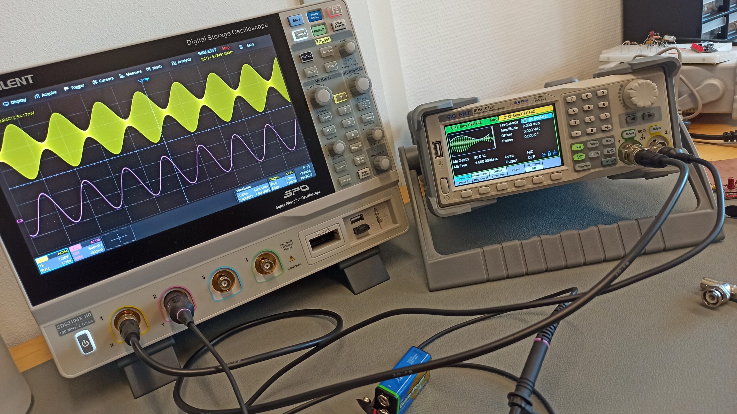
Testing the infinite impedance AM-detector: 10.7 MHz AM signal with 80 % modulation depth at 1.5 kHz
The following circuit was used for testing purposes:
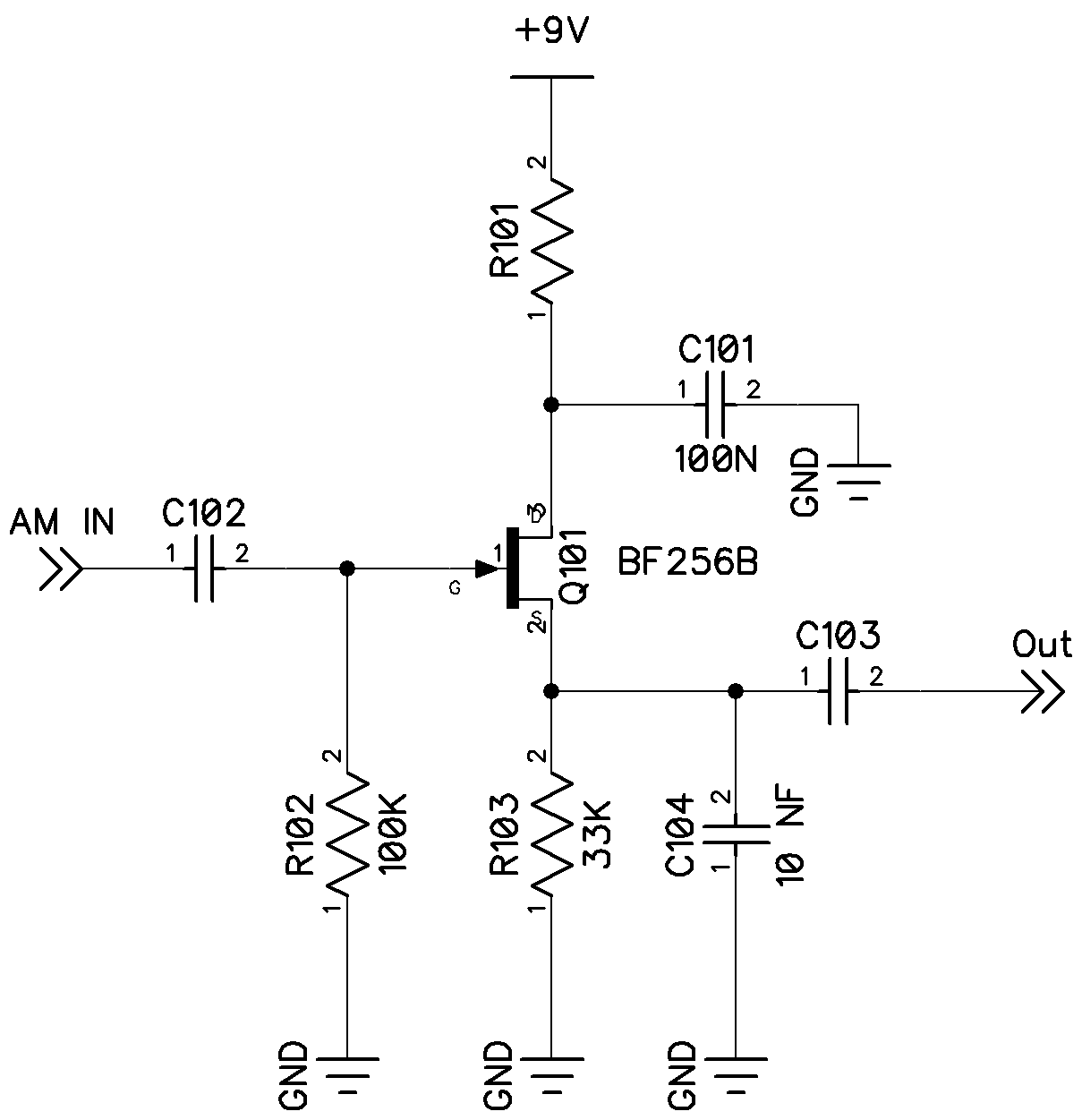
Schematic of the JFET-based infinite impedance detector used in my experiments. R101, C102 and C103 have been omitted in the test circuit.
The working principle is rather simple: The active device, in this case a BF256B JFET, is self-biased by R103 in a way, that the gate to source voltage is essentially equal to the pinch-off voltage of the JFET. Therefore, the negative half-wave of the incoming AM-signal will have little to no effect on the voltage seen over R103. The positive half-wave, however, allows the JFET to conduct more. Thus the source voltage will follow the positive half-wave of the AM-signal applied to the gate of the JFET. The impedance “seen” by the AM-source is solely the (typically very high) gate impedance of the JFET in parallel with R102 (100 K). The previous stage is, therefore, not loaded all too much by the infinite impedance detector.

JFET-based infinite impedance detector for AM demodulation using a BF256B
C104 plays a critical role in the demodulation process: Its job is to low-pass filter in order to remove the rf-component (AM carrier) contained in the positive half-wave. If the value of C104 is chosen too high, the higher audio components will also be surpressed. If, on the other hand, the value of C104 is too low, the AM carrier may not be surpressed satisfactorily. 10 nF works fine for AM-voice transmissions with a cut-off of about 3 kHz. For broadcast AM-signals, the value should be lowered significantly. Literature on vaccum tube implementations of this circuit suggest that the time-constant of R103 and C104 should be chosen to be several times the period of the lowest carrier frequency.
R101, C102 and C103 have been omitted in my test-circuit. R101 should be around 100 Ohms. C103 should be chosen so that the lowest frequency components of the audio signal will not be impeded. C102 is not too critical, 100 nF will be fine for an intermediate frequency (IF) of 455 kHz or higher.
Test Results
For the first test I used a common IF-frequency of 455 kHz. The 455 kHz was amplitude modulated with a single 1.5 kHz tone at a 80 % modulation depth. The signal was then fed directly from the SDG 1032X signal generator into the gate of the previously shown circuit.
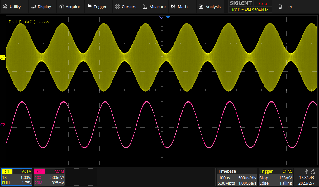
Yellow trace: 455 kHz carrier, amplitude modulated at 80 % depth with a single 1.5 kHz tone. Purple trace: Demodulated audio signal from the infinite impedance detector
As shown on oscilloscope, the 1.5 kHz tone was demodulated perfectly. The amplitude of the input signal could be varied between about 500 mVpp and 4 Vpp without any visible distortion. Out of curiosity I checked if this circuit can also handle a IF-frequency of 10.7 MHz.
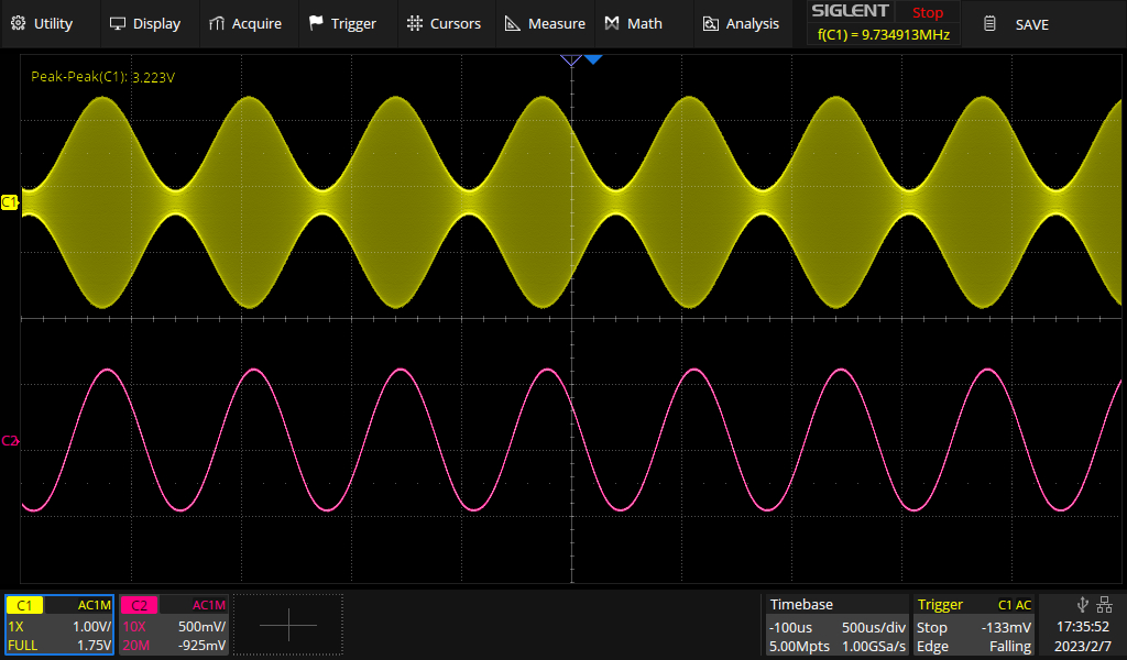
Yellow trace: 10.7 MHz carrier, amplitude modulated at 80 % depth with a single 1.5 kHz tone. Purple trace: Demodulated audio signal from the infinite impedance detector
As shown above, an AM-modulated signal at an IF of 10.7 MHz is also not a problem fo this circuit. As a matter of fact, the circuit actually worked well up to 30 MHz. However, a drop-off of the output amplitude was observed starting at around 20 MHz.
YouTube-Video
Due to popular demand, I published a YouTube-Video about the JFET-based infinite impedance detector on my channel:
Links and Sources:
[1] Chaffe, E. L. Cobine, J. D., Mimno, H. R., Cooke, S. P., Morris, L. W., Cornett, R. O., Stockman, H., Githens, S., Tatum, G. R., LeCorbeiller, P. E., Wing, A. H., (1947): Electronic Circuits and tubes: By the Electronics Training Staff of the Cruft Laboratory, Harvard Univ., New-York, U.S.A.: McGraw-Hill Book Company, inc.
[2] Scerri, F. (2006). High Fidelity AM Reception. Elliott Sound Products. Retrieved July 29, 2022, from: https://sound-au.com/articles/am-radio.htm
Westerhold, S. (2023), "JFET-based infinite impedance detector for AM-demodulation". Baltic Lab High Frequency Projects Blog. ISSN (Online): 2751-8140., https://baltic-lab.com/2023/02/jfet-based-infinite-impedance-detector-for-am-demodulation/, (accessed: June 25, 2026).

- Conducted Emissions on the Bench: Implementing the CISPR 25 Voltage Method - December 15, 2025
- WebP-Images without Plugin - January 14, 2025
- Firewall Rules with (dynamic) DNS Hostname - January 14, 2025
Dan
`Thank you a great site and clear explanations.
Would you mind commenting on whether the JFET infinite impedance detector circuit needs a gate resistor?
I have seen many infinite impedance detector designs that omit the gate resistor and was wondering if this is a good idea or a bad idea.
Thank you!
Sebastian
Hi Dan! Good question. The short answer: It depends. The long answer: The circuit configuration used in my circuit is a so called “self biasing” configuration. The source resistor will elevate the source voltage above ground level, and therefore the gate voltage below the virtual ground at the source of the JFET. For this to work, there has to be a DC path from the gate to ground. That’s the purpose of the gate resistor. It can be omitted if a different DC path to ground is provided. For instance, in the corresponding YouTube video, I show a different circuit with a 455 kHz IF transformer on the gate. In that instance, the gate resistor could be omitted. However, a gate resistor may still be used to force a known impedance on the gate side and provide some degree of stability for high gain stages.
Dan
Ok, that makes sense. I see now that many of the circuits that omit the gate resistor have the gate connected to ground through the preceding transformer or the antenna. Thanks.
Greg
But 102 resistor would be 1000 ohms and not 100 000 ohms like on your schematic or I am missing something?
Sebastian
R102 is the part number in the schematic, not in any way related to the actual value. You’ll note the resistors being numbered R101, R102, R103 and the caps being numbered C101 through C104. The value of R102 is 100 K Ohms as indicated in the schematic.
Greg
Ok thanks
OCT
I put a 2SC170 Rs= 750ohms Rg= 47Koms. A 200ohms 2* ceramic + 2 electrolytic double filtered 4 caps on VDD. Low noise !
Distortions perhaps lite bit higher but low noise. For DX perhaps.
so R101=200ohms
R102=47 Kohms
R103= 750 ohms
C104 =200nF
C103=10uF
Audio amp. 1K optimized input impedance for best low noise performance