General Overview
For my experiments, I used uBlox NEO M6, M7 and M8 modules. The modules were connected to a Laptop using a FT232RL-based UART to USB converter. Using the uBlox u-center software, the Timepulse 5 settings were adjusted to generate 10 kHz and 100 kHz signals with a duty cycle of 50 %. The generated commands were observed using the binary console view of the u-center software.

Setting the Timepulse 5 settings using the uBlox u-center software. Commands sent to the NEO-6 GPS module can be observed in the binary console view.
Those binary commands were then translated to C++ compatible arrays. These commands can now be sent to the GPS-modules using an Arduino quite easily. For instance, the command array to set Timepulse 5 to generate a 10 kHz reference signal with 50 % duty cycle, synchronized to UTC time if the receiver has a valid position fix is as follows:
// UBX CFG-TP5: Set 10 kHz, 50 uS Pulses (50 % duty-cycle), Synch UTC-Time, no output if GPS unlocked

byte TP5_10K_LOCK[]{0xB5, 0x62, 0x06, 0x31, 0x20, 0x00, 0x00, 0x01, 0x00, 0x00, 0x32, 0x00, 0x00, 0x00, 0x01, 0x00, 0x00, 0x00, 0x10, 0x27, 0x00, 0x00, 0x00, 0x00, 0x00, 0x00, 0x32, 0x00, 0x00, 0x00, 0x00, 0x00, 0x00, 0x00, 0x7F, 0x00, 0x00, 0x00, 0x73, 0xF3};
Sending this command to the GPS-module using the inbuilt UART can be accomplished as follows:
Serial.write(TP5_10K_LOCK, sizeof(TP5_10K_LOCK));
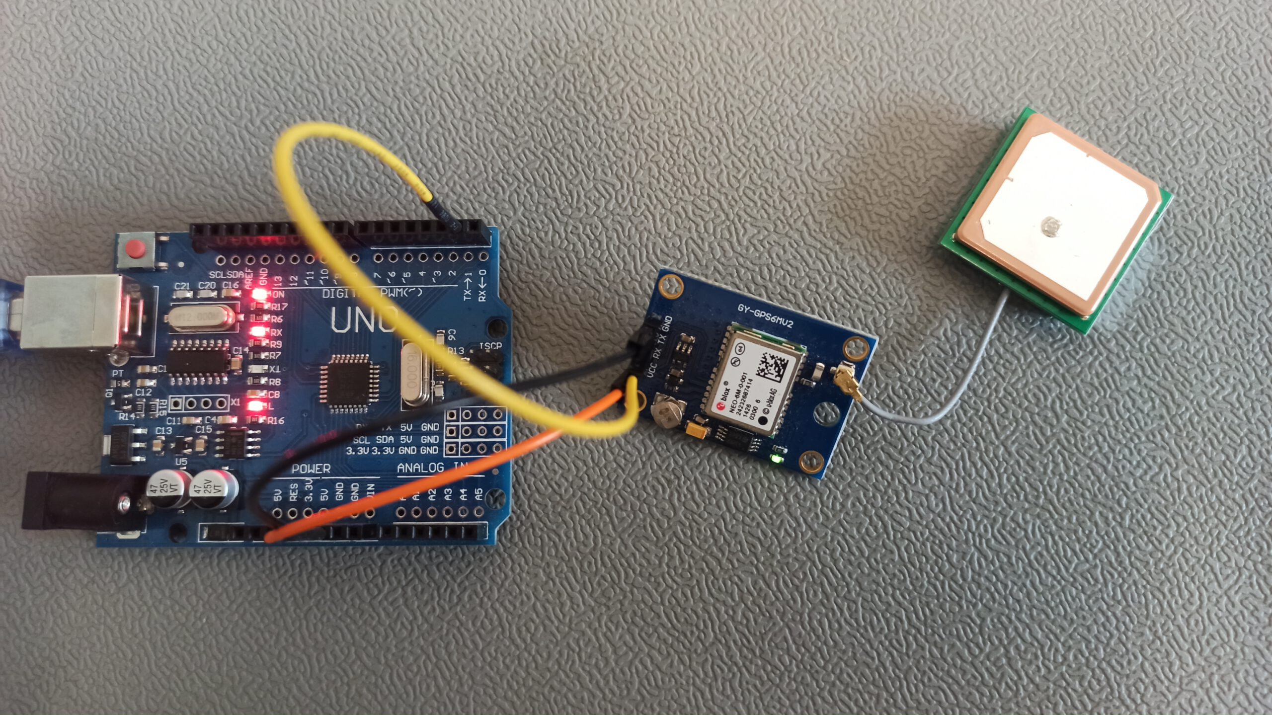
uBlox NEO-6 GPS module connected to an Arduino Uno for dynamic Timepulse 5 setting.
Another useful setting for GPS-locked frequency references is the CFG-NAV5 setting. It can be used to set the navigation mode to stationary.
// CFG-NAV5: Set navigation mode to stationary

byte CFG_NAV5_STATIONARY[] = { 0xB5, 0x62, 0x06, 0x24, 0x24, 0x00, 0xFF, 0xFF, 0x02, 0x03, 0x00, 0x00, 0x00, 0x00, 0x10, 0x27, 0x00, 0x00, 0x05, 0x00, 0xFA, 0x00, 0xFA, 0x00, 0x64, 0x00, 0x2C, 0x01, 0x00, 0x3C, 0x00, 0x00, 0x00, 0x00, 0x00, 0x00, 0x00, 0x00, 0x00, 0x00, 0x00, 0x00, 0x4E, 0x60 };
Note that all settings, including Timepulse 5 and CFG-NAV5, are volatile. That means the settings are lost upon power-cycling the module. This can be avoided by permanently storing the adjusted settings using the CFG-CFG-command.
// UBX CFG-CFG: Save all. BBR + FLASH:
byte CFG[] = {0xB5, 0x62, 0x06, 0x09, 0x0D, 0x00, 0x00, 0x00, 0x00, 0x00, 0xFF, 0xFF, 0x00, 0x00, 0x00, 0x00, 0x00, 0x00, 0x03, 0x1D, 0xAB };
After sending the CFG-CFG-command, all settings will be permanently stored and retrieved upon power-up. Therefore, a microcontroller is not necessary for operating a uBlox GPS-module as frequency reference. The settings can be adjusted dynamically during operation in order to generate different reference frequencies as needed.
Test Results
A simple and straight-forward Arduino sketch was written to test the commands on various uBlox modules. The code sets the Timepulse 5 output frequency to 10 kHz, the navigation mode to stationary and stores the settings permanently. It then goes on to change between 10 kHz and 100 kHz every 10 seconds. The Timepulse output was connected to an oscilloscope and the resulting waveforms were observed. As shown in the images below, the module successfully accepted the commands and alternatingly put out 10 kHz and 100 kHz signals when locked to a valid GPS-source.
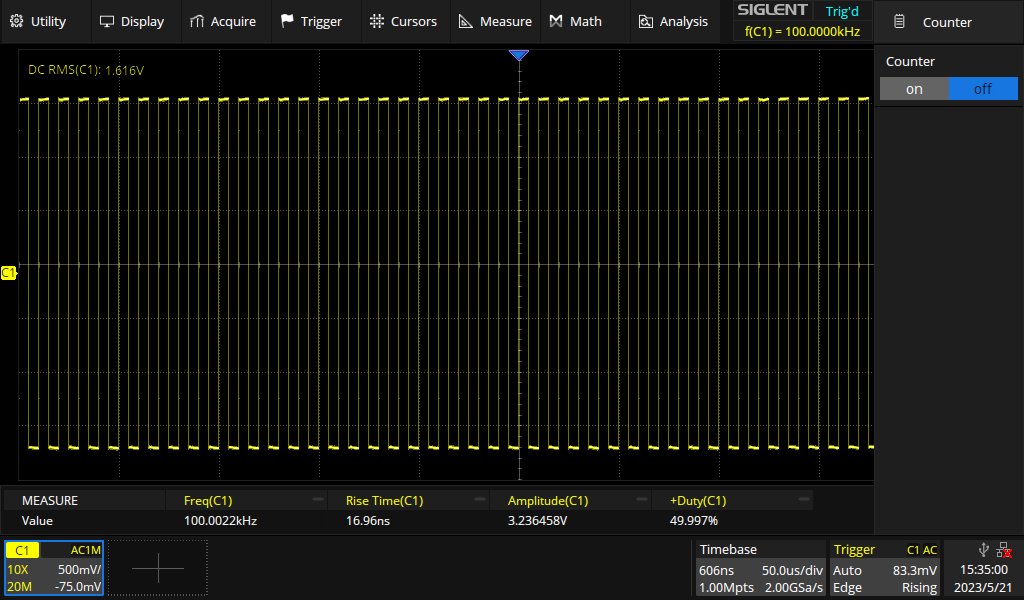
100 kHz, 50 % duty-cycle output from a uBlox NEO-6M GPS module
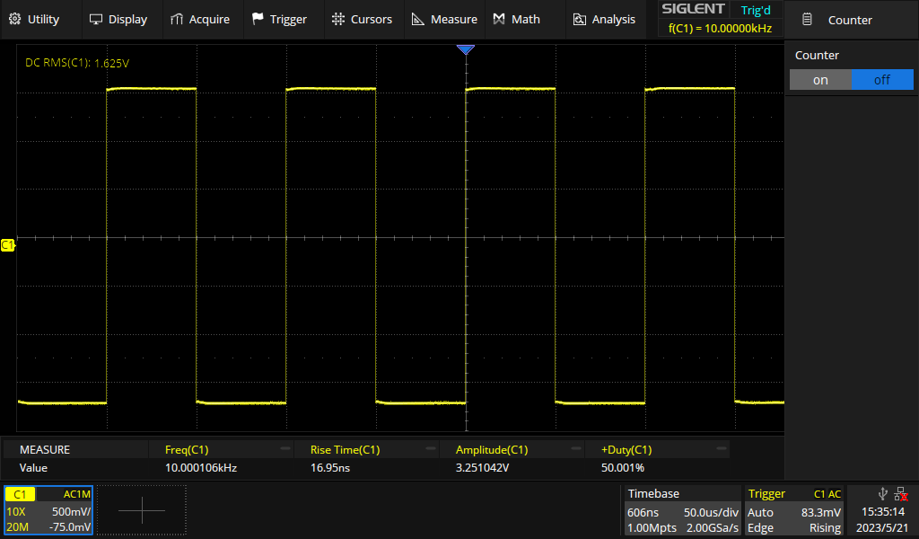
10 kHz, 50 % duty-cycle output from a uBlox NEO-6M GPS module
Commands
Here is a list of useful commands in array-form for the Arduino IDE:
// UBX CFG-CFG: Save all. BBR + FLASH:byte CFG[] = { 0xB5, 0x62, 0x06, 0x09, 0x0D, 0x00, 0x00, 0x00, 0x00, 0x00, 0xFF, 0xFF, 0x00, 0x00, 0x00, 0x00, 0x00, 0x00, 0x03, 0x1D, 0xAB };// CFG-NAV5: Set navigation mode to stationarybyte CFG_NAV5_STATIONARY[] = { 0xB5, 0x62, 0x06, 0x24, 0x24, 0x00, 0xFF, 0xFF, 0x02, 0x03, 0x00, 0x00, 0x00, 0x00, 0x10, 0x27, 0x00, 0x00, 0x05, 0x00, 0xFA, 0x00, 0xFA, 0x00, 0x64, 0x00, 0x2C, 0x01, 0x00, 0x3C, 0x00, 0x00, 0x00, 0x00, 0x00, 0x00, 0x00, 0x00, 0x00, 0x00, 0x00, 0x00, 0x4E, 0x60 };// UBX CFG-TP5 Timepulse 5: 10 kHz, 50 uS (50 % duty cycle), synch to UTC Time, No Putput when unlockedbyte TP5_10K_LOCK[]{ 0xB5, 0x62, 0x06, 0x31, 0x20, 0x00, 0x00, 0x01, 0x00, 0x00, 0x32, 0x00, 0x00, 0x00, 0x01, 0x00, 0x00, 0x00, 0x10, 0x27, 0x00, 0x00, 0x00, 0x00, 0x00, 0x00, 0x32, 0x00, 0x00, 0x00, 0x00, 0x00, 0x00, 0x00, 0x7F, 0x00, 0x00, 0x00, 0x73, 0xF3 };// Timepulse 5: 100 kHz, 5 uS (50 % duty cycle), synch to UTC Time, No Putput when unlockedbyte TP5_100K_LOCK[]{ 0xB5, 0x62, 0x06, 0x31, 0x20, 0x00, 0x00, 0x01, 0x00, 0x00, 0x32, 0x00, 0x00, 0x00, 0x01, 0x00, 0x00, 0x00, 0xA0, 0x86, 0x01, 0x00, 0x00, 0x00, 0x00, 0x00, 0x05, 0x00, 0x00, 0x00, 0x00, 0x00, 0x00, 0x00, 0x7F, 0x00, 0x00, 0x00, 0x36, 0x36 };// UBX CFG-TP5 Timepulse 5: 10 kHz, 50 uS (50 % duty cycle), synch to UTC Time, free running 10 kHz if unlockedbyte TP5_10K[] = { 0xB5, 0x62, 0x06, 0x31, 0x20, 0x00, 0x00, 0x01, 0x00, 0x00, 0x32, 0x00, 0x00, 0x00, 0x10, 0x27, 0x00, 0x00, 0x10, 0x27, 0x00, 0x00, 0x32, 0x00, 0x00, 0x00, 0x32, 0x00, 0x00, 0x00, 0x00, 0x00, 0x00, 0x00, 0x7F, 0x00, 0x00, 0x00, 0xDB, 0xFC };// UBX CFG-TP5 Timepulse 5: 100 kHz, 5 uS (50 % duty cycle), synch to UTC Time, free running 100 kHz if unlockedbyte TP5_100K[] = { 0xB5, 0x62, 0x06, 0x31, 0x20, 0x00, 0x00, 0x01, 0x00, 0x00, 0x32, 0x00, 0x00, 0x00, 0xA0, 0x86, 0x01, 0x00, 0xA0, 0x86, 0x01, 0x00, 0x05, 0x00, 0x00, 0x00, 0x05, 0x00, 0x00, 0x00, 0x00, 0x00, 0x00, 0x00, 0x7F, 0x00, 0x00, 0x00, 0x61, 0x8E };
Arduino Code
/** uBlox u-blox NEO-6M / NEO-7M** Copyright (C) 2022 Westerhold, S. (AI5GW)* ORCID: https://orcid.org/0000-0001-7965-3140* Web (EN): https://baltic-lab.com** This program is free software: you can redistribute it and/or modify* it under the terms of the GNU General Public License as published by* the Free Software Foundation, either version 3 of the License, or* (at your option) any later version.*/// CFG-NAV5: Set navigation mode to stationarybyte CFG_NAV5_STATIONARY[] = { 0xB5, 0x62, 0x06, 0x24, 0x24, 0x00, 0xFF, 0xFF, 0x02, 0x03, 0x00, 0x00, 0x00, 0x00, 0x10, 0x27, 0x00, 0x00, 0x05, 0x00, 0xFA, 0x00, 0xFA, 0x00, 0x64, 0x00, 0x2C, 0x01, 0x00, 0x3C, 0x00, 0x00, 0x00, 0x00, 0x00, 0x00, 0x00, 0x00, 0x00, 0x00, 0x00, 0x00, 0x4E, 0x60 };// UBX CFG-CFG: BBR + FLASH:byte CFG[] = { 0xB5, 0x62, 0x06, 0x09, 0x0D, 0x00, 0x00, 0x00, 0x00, 0x00, 0xFF, 0xFF, 0x00, 0x00, 0x00, 0x00, 0x00, 0x00, 0x03, 0x1D, 0xAB };// UBX CFG-TP5 Timepulse 5: 10 kHz, 50 uS (50 % duty cycle), synch to UTC Time, No Putput when unlockedbyte TP5_10K_LOCK[]{ 0xB5, 0x62, 0x06, 0x31, 0x20, 0x00, 0x00, 0x01, 0x00, 0x00, 0x32, 0x00, 0x00, 0x00, 0x01, 0x00, 0x00, 0x00, 0x10, 0x27, 0x00, 0x00, 0x00, 0x00, 0x00, 0x00, 0x32, 0x00, 0x00, 0x00, 0x00, 0x00, 0x00, 0x00, 0x7F, 0x00, 0x00, 0x00, 0x73, 0xF3 };// Timepulse 5: 100 kHz, 5 uS (50 % duty cycle), synch to UTC Time, No Putput when unlockedbyte TP5_100K_LOCK[]{ 0xB5, 0x62, 0x06, 0x31, 0x20, 0x00, 0x00, 0x01, 0x00, 0x00, 0x32, 0x00, 0x00, 0x00, 0x01, 0x00, 0x00, 0x00, 0xA0, 0x86, 0x01, 0x00, 0x00, 0x00, 0x00, 0x00, 0x05, 0x00, 0x00, 0x00, 0x00, 0x00, 0x00, 0x00, 0x7F, 0x00, 0x00, 0x00, 0x36, 0x36 };void setup() {Serial.begin(9600);// Set Timepulse output to 100 kHz, 50 % duty-cycleSerial.write(TP5_10K_LOCK, sizeof(TP5_10K_LOCK));// Set navigation mode to stationarySerial.write(CFG_NAV5_STATIONARY, sizeof(CFG_NAV5_STATIONARY));// Store settings permanentlySerial.write(CFG, sizeof(CFG));}// loop switches between 10 kHz and 100 kHz every 10 secondsvoid loop() {Serial.write(TP5_10K_LOCK, sizeof(TP5_10K_LOCK));delay(10000);Serial.write(TP5_100K_LOCK, sizeof(TP5_100K_LOCK));delay(10000);}
Westerhold, S. (2023), "Program uBlox GPS-module timepulse frequency (dynamically) with an Arduino". Baltic Lab High Frequency Projects Blog. ISSN (Online): 2751-8140., https://baltic-lab.com/2023/05/set-ublox-neo-gps-module-timepulse-frequency-dynamically-with-an-arduino/, (accessed: June 26, 2026).

- Conducted Emissions on the Bench: Implementing the CISPR 25 Voltage Method - December 15, 2025
- WebP-Images without Plugin - January 14, 2025
- Firewall Rules with (dynamic) DNS Hostname - January 14, 2025
Peter Halverson
Dear Sebastian,
Thank you for posting this tutorial.
It could be very helpful to a project I’m working on – observing the pulsar in the Crab Nebula with a small telescope. Accurate timing is needed to track the phase of the pulses from the neutron star.
I have a couple questions:
1) Where did you find the commands for the uBlox NEO M6, M7 and M8 modules?
2) What other frequencies can be generated?
For example, is it possible to generate 30 Hz? (The pulsar spins at just under 30 rotations per second.)
Sincerely,
Peter Halverson
Sebastian
Hi Peter! I found the commands by observing the output from the uBlox u-center software (as described in the article). So basically, I used the uBlox-center to adjust the settings that I needed and used the output to copy the generated commands. And yes, 30 Hz is possible. However, make sure that 30 Hz is a full integer fraction of the internal oscillator of the uBlox GPS receiver. It works with non-integer values but there may be some jitter in the timing. That said, whether or not that really is important, depends on the timing accuracy needed.
mauro
hi, how do you calculate the checksum?
Sebastian Westerhold
I didn’t calculate it at all, I just repeated the messages from the uBlox u-center software. That said, something like this (completeley untested and unverified) should work as a starting point:
// CFG-RATE (0x06,0x08) packet (without header 0xB5,0x62)
// payload length – 6 (little endian format), update rate 200ms, cycles – 1, reference – UTC (0)
byte packet[] = {0x06, 0x08, 0x06, 0x00, 0x00, 0xC8, 0x00, 0x01, 0x00, 0x00};
byte CK_A = 0;
byte CK_B = 0;
void setup() {
// Initialize serial communication
Serial.begin(9600);
// Compute CK_A and CK_B using the checksum algorithm
for (int i = 0; i < sizeof(packet); i++) { CK_A += packet[i]; CK_B += CK_A; } // Ensure unsigned byte range (0-255) CK_A = CK_A & 0xFF; CK_B = CK_B & 0xFF; // Output the checksum values Serial.print("CK_A: "); Serial.println(CK_A, DEC); // Print CK_A in decimal format Serial.print("CK_B: "); Serial.println(CK_B, DEC); // Print CK_B in decimal format } void loop() { // Nothing to do in loop }