Not too long ago I reviewed ADI’s wideband PLL synthesizer ADF4351 with integrated low phase noise VCO. The ADF4360 series family of synthesizer chips is very similar. The primary difference is their restricted frequency coverage and thus much lower price.
The ADF4360 is an integrated integer-N synthesizer with an integrated voltage controlled oscillator (VCO). The center frequency is set by external inductors. There are 9 chips in the family with 8 different frequency ranges. The frequency range are as follows:
ADF4360-0: 2400 to 2725 MHz
ADF4360-1: 2050 to 2450 MHz
ADF4360-2: 1850 to 2170 MHz
ADF4360-3: 1600 to 1950 MHz
ADF4360-4: 1450 to 1750 MHz
ADF4360-5: 1200 to 1400 MHz
ADF4360-6: 1050 to 1250 MHz
ADF4360-7: 350 to 1800 MHz
ADF4360-8: 65 to 400 MHz
ADF4360-9: 65 to 400 MHz
Even though the ADF4360-8 and ADF4360-9 have the same frequency range, they are a bit different. The ADF4360-9 has an auxiliary divider with division ranges from 2 to 31 on board. The ADF4360-8 has – just like all other ADF4360 – a hardware power down input (CE).
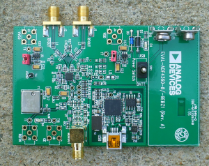
Analog Devices kindly sent me one of their Evaluation Kits for the ADF4360-9 (EV-ADF4360-9EB1Z) for review and evaluation [1].
What I intend to use this chip in is called a Fox-Hunt transmitter. It has very little to do with hunting actual foxes and actually relates to a common radio direction finding exercise. The way this works is that a small transmitter (the “fox”) is hidden somewhere and a group of people will attempt to locate the transmitter. Whoever finds the transmitter first, wins the game.
I want to build a very small transmitter for the 2m amateur radio band (~145 MHz) with just a few miliwatts of output power. With such a low power VHF transmitter, a radio direction finding exercise could be conducted in a small area like a park, or even more challenging, with several transmitters at the same time. A microcontroller is supposed to be in charge of setting the frequency and keying the required station identification (call-sign of the control operator) as required by the FCC.
But now back to the ADF4360. The chip has an SPI compatible 3-wire interface, operates between 3 – 3.6 Volts and its inputs are 1.8 V logic compatible. In other words: this chip will interface with pretty much any microcontroller out there. My project will probably be Atmel AVR or MSP430 based and I program in C. However, I will write example code for Arduino (AVR) / Energia (MSP430) for folks who would like to experiment with it more easily.
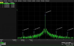
I looked at the output spectrum of the ADF4360-9 set to 400 MHz on a Teledyne LeCroy HDO6054. The phase frequency detector (PFD) frequency is 200 kHz and you can clearly see spurs 200 kHz spaced to both sides of the carrier. The spurs are smaller than -70 dBc and, to be fair, the ADF4360-9 is not correctly terminated. The IC has a differential output and the datasheet warns that the performance of the output signal may be degraded if not both ports are properly terminated with 50 Ohms. In my case, only one port is fed into the 50 Ohm port of the scope. The other port is open.
In any case, -70 dBc is a lot of attenuation. As a matter of fact, the output signal could be transmitted the way it is over the air. The FCC demands in 74 CFR 97.307 (e) that “the mean power of any spurious emission from a station transmitter or external RF power amplifier transmitting on a frequency between 30 – 225 MHz must be at least 60 dB below the mean power of the fundamental.” This is clearly the case.
The eval board comes with a very comfortable software, just like the ADF4351 did. It is very nice to be able to manipulate all registers and parameters and watch what happens right away.
So what’s next? I will design the circuit, design a PCB, and write the necessary software code for the little VHF tracker (“fox”). The project will be an open hardware project. That means you will be able to use my project free of charge for personal use. As soon as that is done, I will post a new article with the entire project in it. Stay tuned!
Links and Sources:
[1] ADF4360-9, ADI: http://www.analog.com/
Westerhold, S. (2013), "Review: Analog Devices ADF4360 PLL Synthesizer". Baltic Lab High Frequency Projects Blog. ISSN (Online): 2751-8140., https://baltic-lab.com/2013/02/review-analog-devices-adf4360-pll-synthesizer/, (accessed: December 27, 2025).
- Conducted Emissions on the Bench: Implementing the CISPR 25 Voltage Method - December 15, 2025
- WebP-Images without Plugin - January 14, 2025
- Firewall Rules with (dynamic) DNS Hostname - January 14, 2025


David Colburn
Could this be used as a 100-150MHz VFO to feed the the Ham It Up v1.0 – RF Upconverter (a HF adapter used with a RTL-SDR USB dongle)?
The Upconverter may be used in-reverse to generate a HF TX signal from a 100-150MHz input.
If so, could this device be modulated for DSB and/or SSB? PSK31, etc?
Thanks!
David KD4E
KF5OBS
David, short answer: yes.
Long answer:
100 – 150 MHz should be possible. I’d have to take a closer look at the manual though if the span may be a bit too big. If it is, the ADF4351 can definitely do it. Modulating the signal directly is really just possible with CW (OOK) FM or PM for that matter. However, since we live in the 21st century, you could add an I/Q modulator and a smart microcontroller and you’d be able to use pretty much any modulation known to man. Analog devices has matching I/Q modulators available.
David Colburn
You are way ahead of me on the I/Q modulator for SSB & DSB, but it’s sure good to know it’s possible, Someone far more technically-astute than I will have to show the way. Sure sounds like exciting possibilities are out there!
OK on the VFO. If I read this correctly then 160-10m would require 101.8 MHz – 130MHz.
http://code.google.com/p/opendous/wiki/Upconverter “If you have a VHF transmitter that operates in the 100MHz to 150MHz range then the Upconverter can be used in reverse as a down-converting mixer to broadcast over 0.5MHz to 50MHz (downconverted 100.5MHz to 150MHz signal).”
Thanks!
anders
Hi, do you have a spectrum analyzer view of the output at say 1GHz?
I’ve been testing an ADF4350 eval-board, and I do get the correct output frequency, but my spectra look like “open loop VCO” spectra with very strong/wide tails. The nice looking spectra I find online with e.g. SPAN of 500kHz and RBW 100Hz have a noise power below -90dBm at just 50Hz offset from the carrier. Like this one:
http://martein.home.xs4all.nl/pa3ake/hmode/dds_refclock.html
I wonder if that kind of performance is doable with ADF4350 or ADF4360? We do have a very stable 10MHz signal/clock in the lab we can use. But perhaps the wenzel-oscillator at 100MHz used in that link is much much better than the VCO in ADF4350/ADF4360??
KF5OBS
The ADF4351 and the ADF4360-X PLLs / VCOs are actually quite clean. Can you post a picture of the output spectrum you are getting? I’ll be more than glad to do the same and then we can compare. It’s possible that either you have a bad board or that it’s an abnormality unique to a certain frequency / frequency range. Remember that you can (and should) configure the loop parameters. I think by default the PFD frequency is 200 kHz. Accordingly, you’re gonna see 200 kHz spurs. If you play around with the loop parameters I am sure that you can minimize the spurs. A modern DDS is probably gonna outperform the ADF4351 and ADF4360 without problems.
anders
I’ve posted my ADF4350 spectrum over here:
http://www.anderswallin.net/2014/03/adf4350-pllvco-and-ad9912-dds-power-spectra/
I am using the 1 GHz output from the ADF4350 as the SYSCLK input for an AD9912 DDS. The DDS output at 100MHz is also show, with two different SYSCLK configurations.
My understanding is that any phase-noise on the SYSCLK will more or less directly show up on the DDS output. So to get the best possible DDS output the 1 GHz SYSCLK needs to be as good as possible.
My DDS output spectra are still quite far away from what is shown in the AD9912 datasheet, or in the results by Martein/PA3AKE that I linked to.
Can you make a measurement of the ADF4350 or ADF4360 with the same settings, SPAN 500 kHz, RBW 100Hz? What is the datasheet phase-noise number for your spectrum analyzer?
thanks!
Anders
Jim Walworth
I need a kickstart with some code written to work on the Arduino IDE interfacing directly to the AD4350 chip. My desired frequency is 2300MHz using the 25MHz PD frequency. I have the arduino ftdi board working well with “blink”. I also have the AD4350 working well using their software and the Eval board. After I get the 2300MHz going, I will want to do a fractional frequency out of 838 MHz. Any help will be appreciated. I am willing to pay for your time as it will greatly shorten my learning curve.