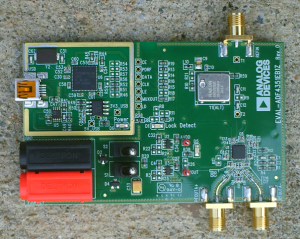
The ADF4351 from Analog Devices (ADI) is a modern wideband PLL synthesizer with integrated low phase noise VCO. It is capable of generating signals between 35 MHz to 4400 MHz with a very low jitter of typical 0.3 ps. ADI agreed to send me the EVAL-ADF4351EB1Z, an evaluation board for the ADF4351, for review purposes. Let’s check it out!
The ADF4351 has an integrated voltage-controlled oscillator (VCO) with a fundamental output frequency ranging from 2200 MHz to 4400 MHz. In addition, divide-by-1/-2/-4/-8/-16/-32/-64 circuits allow the user to generate RF output frequencies as low as 35 MHz. For applications that require isolation, the RF output stage can be muted. The mute function is both pin- and software-controllable. An auxiliary RF output is also available, which can be powered down when not in use. Control of all on-chip registers is through a simple wire interface. The device operates with a power supply ranging from 3.0 to 3.6 V and can be powered down when not in use.
ADI ships the EVAL-ADF4351EB1Z with a USB cable and a CD. The CD contains all software necessary to get started right away. The board itself makes a very clean impression. Despite the surface mount technology, all case styles of the components used can comfortably be handled with appropriate hand soldering tools. This allows for easy application specific modifications.
There are two 4 mm jacks for power (3.75 V to 5.5 V), a small USB connector, and 3 SMA connectors on the board. The first SMA connector serves as reference input for an external reference signal. Alternatively, it can be used as an output for the on-board reference (25 MHz). The other two SMAs are the primary RF output of the ADF4351. It is a differential pair. For best performance, make sure to terminate both outputs correctly (50 Ohms) even if just one output is being used.
Power can either be supplied through the 4 mm banana jacks or the USB port. Switches S1 and S2 are used to select the power source. Switch S1 is used to power the ADF4351 from the external DC connector and switch S2 to power from the USB port. The USB clock can cause spurs in the RF signal if power is derived from the USB port.
Plenty of test points on the board allow easy troubleshooting. An additional 100 mil / 2.54 mm header can be populated to gain easier access to the most important logic signals.
The external loop filter on the eval board has a bandwidth of 35 kHz. This value can easily be changed by changing the value of the corresponding components. The software package ‘ADIsimPLL’ from Analog Devices is a great tool for designing an application specific loop filter.
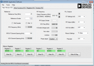
Make sure to install the software from the CD before connecting the evaluation board to the PC for the first time. Once the software is installed properly, connect the board to the PC and start the ADF4351 software package. If the two power LEDs on the board (D5 and D6) do not light up upon connection, verify S1 and S2 for proper selection of the desired power source.
The software is self-explanatory. It allows accessing and manipulating of all functions and registers of the ADF4351. Additionally, the software allows you to use the evaluation board as a sweep generator and it can do frequency hopping between two frequencies.
After trying this board out for a while, I highly recommend this chip. It is small, inexpensive ($8.25, 100 QTY) and extremely simple to integrate.
I can think of many applications for the ADF4351 in the amateur radio community. The ADF4351 a perfect 21st century alternative for older SP5055 based designs. The SP5055 was a very popular synthesizer chip used in many older amateur radio projects.
The chip is predestined to be used as a flexible Local Oscillator (LO) in amateur radio transverters. A flexible LO frequency allows to cover more bandwidth in the target frequency range than the IF transceiver itself offers. Paired with a baseband processor and a power amplifier, this chip easily transform into an inexpensive amateur television (ATV) transmitter. I will show some practical designs and applications in future articles. Stay tuned!
Links and Sources:
[1] ADF4351, ADI: http://www.analog.com/
[2] ADF4351 Datasheet, ADI: http://www.analog.com/
[3] Evaluation Board User Guide, ADI: ftp://ftp.analog.com/
Westerhold, S. (2012), "Review: Analog Devices ADF4351 ". Baltic Lab High Frequency Projects Blog. ISSN (Online): 2751-8140., https://baltic-lab.com/2012/12/review-analog-devices-adf4351/, (accessed: June 2, 2025).
- WebP-Images without Plugin - January 14, 2025
- Firewall Rules with (dynamic) DNS Hostname - January 14, 2025
- Restoring proxied visitor IPs from Cloudflare - December 26, 2024


Review: Analog Devices ADF4360 PLL Synthesizer | KF5OBS /IP
[…] too long ago I reviewed ADI’s wideband PLL synthesizer ADF4351 with integrated low phase noise VCO. The ADF4360 series family of synthesizer chips is very […]
Ashish Roy
Well your review gives all the necessary information about the ADF4351 eval. board which is also there in the user guide…but no information is provided about programming the device using a micro controller with serial interface. Does it contain an EEPROM so that once programmed through the PC (using the given software), it can be used as a standalone system for LO generation(as an example).Or will it always require a controller interface to give the divider settings.
KF5OBS
Ashish, I admit that the review is very brief. The device does not contain an EEPROM. However, you can use a very cheap microcontroller that doesn’t do anything but writing the right registers and goes to sleep. The interface is a standard SPI interface and the exact way of programming data to the chip via SPI is explained in the datasheet. I will shortly post sample codes for Atmel AVR / MSP430 based MCUs using Arduino (AVR) / Energia (MSP430) for folks who would like to experiment with it more easily.
Gerhard Steuerwald
Hi,can I also get the software for an AVR-controller?
I have got a pcb with the rf circuit and want to realize the usb-spi interface.
Thanks and regards
Brock
Did you ever get around to programming the ADF4351 via SPI? I’ve read the data sheet but I don’t understand how the prescaler and feedback select contribute to the calculation of MOD seen in the software that comes with the development board.
Rajendra
pls send the sample code of ADF4351(spi) to [email protected]
Andrey
pls send the sample code of ADF4351(spi) to [email protected]
Hugo
Can you send a code for arduino of adf4351? Thanks a lot [email protected]
Euclides Chuma
Good post. Please, can you send a code for arduino to control adf4351? Best regards [email protected]
bobby tri
Can you send a code/sketch for arduino of adf4351? Thanks a lot [email protected]
Pollux
Can you send me the code please?
Thank you a lot,
[email protected]
oraesatta
Well, you know, leaving own email address helps on these cases… andrea(at)awd.it
Hi there – maybe I’m too late but if someone has written some Arduino code/library may I receive some hints/links? Many thank in advance.
– Andrea
Gary Beech
Hi have the Arduino code been published.
Thank you Gary vk2kyp
jouan
it there “somewhere” the ARDUINO code ?
thanks F1CHF
Selim
where can I find code of that project ?
Selim
if someone has got please could send it to [email protected]