Abracon’s AOCJY1 series offers various through-hole OCXOs with several possible frequencies between 10 MHz and 100 MHz. Available frequencies include 10.00 MHz, 12.80 MHz, 13.00 MHz, 26.00 MHz, 38.88 MHZ, 40 MHz and 100 MHz. They come with a standard stability of ±500 ppb over -40°C to +75°C. The long-term aging over the course of 10 years is ±3 ppm or better. Abracon claims excellent close-in phase noise (-145 dBc/Hz Typical @1k Hz offset; 10MHz carrier) for these OCXOs.
Several models with tighter stability and different supply voltages are available. For instance, a tighter temperature stability of ±50.0 ppb over 0°C to +50°C is available. Two supply voltage options are available, 3.3 Volts or 5 Volts (option ‘A’). RF output options include CMOS level rectangular and sine wave (option ‘SW’). For more details, see the datasheet [1].
Prices vary greatly with options and fluctuate a lot between different distributors. I bought two AOCJY1 for 10 MHz with CMOS level output, 5 V supply voltage, and ±50.0 ppb over 0°C to +50°C for some experimentation. Newark sells them for about $80 per piece at the moment [2]. At the time when I bought them, they were almost twice as much.
The circuit I used is very simple. Two voltage regulators stabilize the supply voltage to the required 5 Volts. Since linear voltage regulators have the unfortunate habit of introducing noise into the supply voltage, I used two regulators in series and implemented an output RC low pass filter (R1, C5) in order to drastically reduce this effect.
Even though the output drive level is probably high enough for most applications (2 dBm @ 50 Ohms), I decided to add an output buffer amplifier. This is for two reasons: First, I intend to drive about 5 devices at the same time with it. Secondly, I want to make sure that any shorts, surges or other abnormalities will rather damage the output buffer amplifier than the OCXO itself.
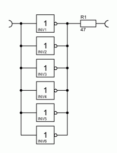
I decided to use all six gates of a 74HCT04 inverter for this purpose. That way the output signal is on TTL level, acceptably isolated from the OCXO and has plenty of drive power.
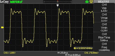
The 47 Ohm resistor at the amplifiers output is to match the output close to 50 Ohms. If you need a sine wave output for your target application, simply add a 10 MHz low pass filter network at the output of the buffer amplifier. This is what the output signal of the buffer amplifier looks like:
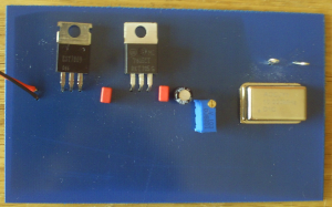
The ringing is caused by the extreme impedance mismatch between the probe (1 MΩ) and the buffer amplifier’s output (~ 50 Ω). Instead of using perforated PC-Board, I decided to actually make a nice PCB for this project. Here’s the result:
Links and Sources:
[1] AOCJY1 Series Datasheet, Abracon: http://www.abracon.com/
[2]: Newark, AOCJY1A-10.000MHZNewark.com
Westerhold, S. (2012), "AOCJY1 series high stability OCXOs from Abracon". Baltic Lab High Frequency Projects Blog. ISSN (Online): 2751-8140., https://baltic-lab.com/2012/09/aocjy1-series-high-stability-ocxos-from-abracon/, (accessed: February 3, 2026).
- Conducted Emissions on the Bench: Implementing the CISPR 25 Voltage Method - December 15, 2025
- WebP-Images without Plugin - January 14, 2025
- Firewall Rules with (dynamic) DNS Hostname - January 14, 2025


Adam
Thanks for this post. I have a question about the voltage regulator noise. You mention using two regulators (a 9V and a 5V) in series to reduce noise. I would expect two components to result in a worse noise figure due to Friis’ formula. Does this work because the total noise from stepping 12V->9V then 9V->5V ends up less than doing 12V->5V in a single regulator?
Thanks,
Adam
KF5OBS
Adam,
quite honestly, I have never verified this to be true. I have read this to be true on several occasions in electronic literature but have never questioned it. Time to change this and conduct a little experiment. Give me some time and I will actually hook up test equipment to a single linear regulator and then two in series and see what the numbers say. I guess a perfect approach to this would be a low-noise LDO to begin with.
Review: Abracon Sync’n Go – Portable Precision Frequency Reference | KF5OBS /IP
[…] too long ago, I wrote an article about the AOCJY1 series high stability OCXOs from Abracon. While I was writing that particular article, I visited the manufacturer’s webpage and found […]