Every passive probe and every piece of coax cable has a specific capacitance. This fact is simply given by the laws of physics. A Teledyne LeCroy PP016 (300 MHz BW) probe, for instance, has a maximum input capacitance of 12 pF in the 1:10 position. Probes rated for smaller bandwidths often have an even higher input capacitance.
12 pF doesn’t sound like much at all. At 1 GHz, though, this capacitance acts like a load with a resistance of 13.26 Ohms. Correctly, this would be referred to as a reactance and not as a resistance, though. Needless to say, 13.26 Ohms is way too low and, in most cases, will put too much weight on whatever it is we measure. Remember, our goal is usually to have the highest possible impedance to put the least possible load on the stage we are testing.
Of course there are commercial solutions for this problem available. Look at the Teledyne LeCroy PP066 ‘High Bandwidth Passive Probe’ for up to 7.5 GHz, for instance [1]:
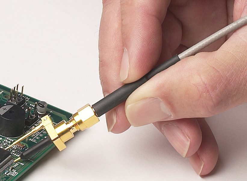
Teledyne LeCroy PP066 transmission line for up to 7.5 GHz
The probe really looks like a modified SMA connector with a tip attached to the center pin and a grounding pin connected to the shield. A probe like this costs more than an inexpensive entry-level oscilloscope itself. So can we built something like this at home? Obviously I wouldn’t write this article if we couldn’t, so here is what I did.
While looking for a good starting point, I stumbled across my box of small semi-rigid coax jumpers [2]. Semi-rigid cable has a very low specific capacitance of around 0.1 pf/mm. That would mean a short piece of about 2.5 cm or 1″ would barely have 2.5 pF of capacitance. At 1 GHz, that would mean a reactive load of 63.66 Ohms. Since most circuit stages in that frequency range work with a impedance of 50 Ohms anyway, the line impedance is high compared to the 50 Ohms. So how do we transform the coax into a cheap probe?
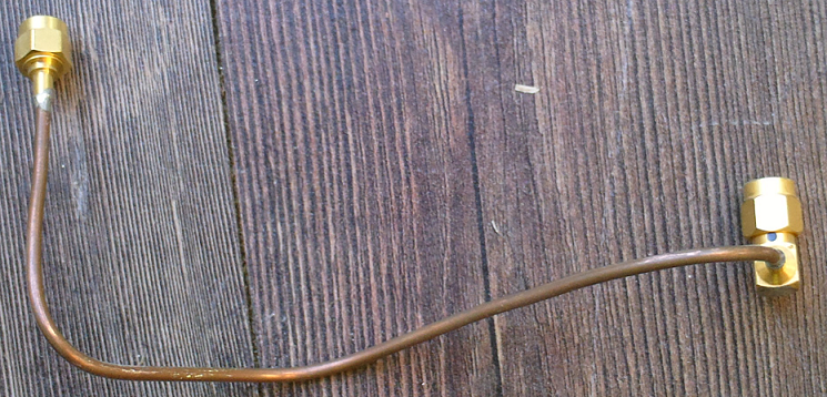
Semi-rigid coax cable with SMA connectors
The first thing I did was carefully stripping a piece of the copper shield off. I used a normal pocket knife for this purpose. To my surprise, it’s fairly easy to cut the shield without damaging the dielectric too much. Next, I stripped some of the dielectric to expose a few mm of the center conductor.
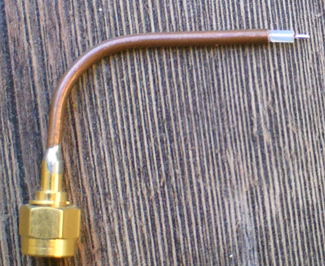
Cut-off semi-rigid coax cable
The only thing that was missing now was a ground lead. Thanks to the solid copper shield, that was an easy task. I simply soldered a piece of silver plated copper wire to the shield.

Cut-off semi-rigid coax cable with ground lead as improvised GHz probe
The result doesn’t look nearly as fancy as the commercial solution, but it’s cheap and easy to make. However, I’d like to point out that I was not doing anything fancy with this makeshift probe and cannot really give a performance feedback. Directly connected to a frequency counter, I could successfully probe a 1.4 GHz and a 2.8 GHz signal. I will try to probe the LOs of C- and Ku-Band LNBs shortly and post back how well that worked. But for less than $1 investment, this is certainly a nice thing to try, though.
Links and Sources:
[1] PP066 High Bandwidth
Passive Probe, Teledyne LeCroy: http://teledynelecroy.com/
[2] Semi Rigid Cable, eBay: http://www.ebay.com/
Westerhold, S. (2013), "DIY Passive Probe for the GHz range". Baltic Lab High Frequency Projects Blog. ISSN (Online): 2751-8140., https://baltic-lab.com/2013/01/diy-passive-probe-for-the-ghz-range/, (accessed: May 1, 2026).

- Conducted Emissions on the Bench: Implementing the CISPR 25 Voltage Method - December 15, 2025
- WebP-Images without Plugin - January 14, 2025
- Firewall Rules with (dynamic) DNS Hostname - January 14, 2025
PicoNano
This one is quite similar to the commercial probe:
http://koti.mbnet.fi/jahonen/Electronics/DIY%201k%20probe/
Works nicely with digital stuff, don’t know about RF-compatibility.
JP
The closer you solder the ground lead to the end will improve performance. As well as shortening the non shielded lead. Both will reduce the inductive spike that you will see at the probe tip.
oli
You should add an 450Ω 0402 resistor on the tip. Then you its would be really usable…