UPDATE: There also is a German version of this article and the corresponding YouTube video available on my German blog: Einstellbares 30 kV Hochspannungs-Netzeil im Eigenbau
Homebrew 5 kV to 30 kV high voltage power supply.
Overview
The foundation of this project is a commercial laser power supply. It’s a 50 Watt CO2 laser supply made by the manufacturer VEVOR [1]. According to the manufacturer, it has a starting voltage of 20 kV and a maximum output current of 20 mA. In reality, the supply can start as low as 5 kV, produces voltages in excess of 30 kV and provides output currents of over 30 mA. These operating parameters seem perfect for laser and spark gap experiments.
Front view of the homebrew 5 kV to 30 kV high voltage power supply.
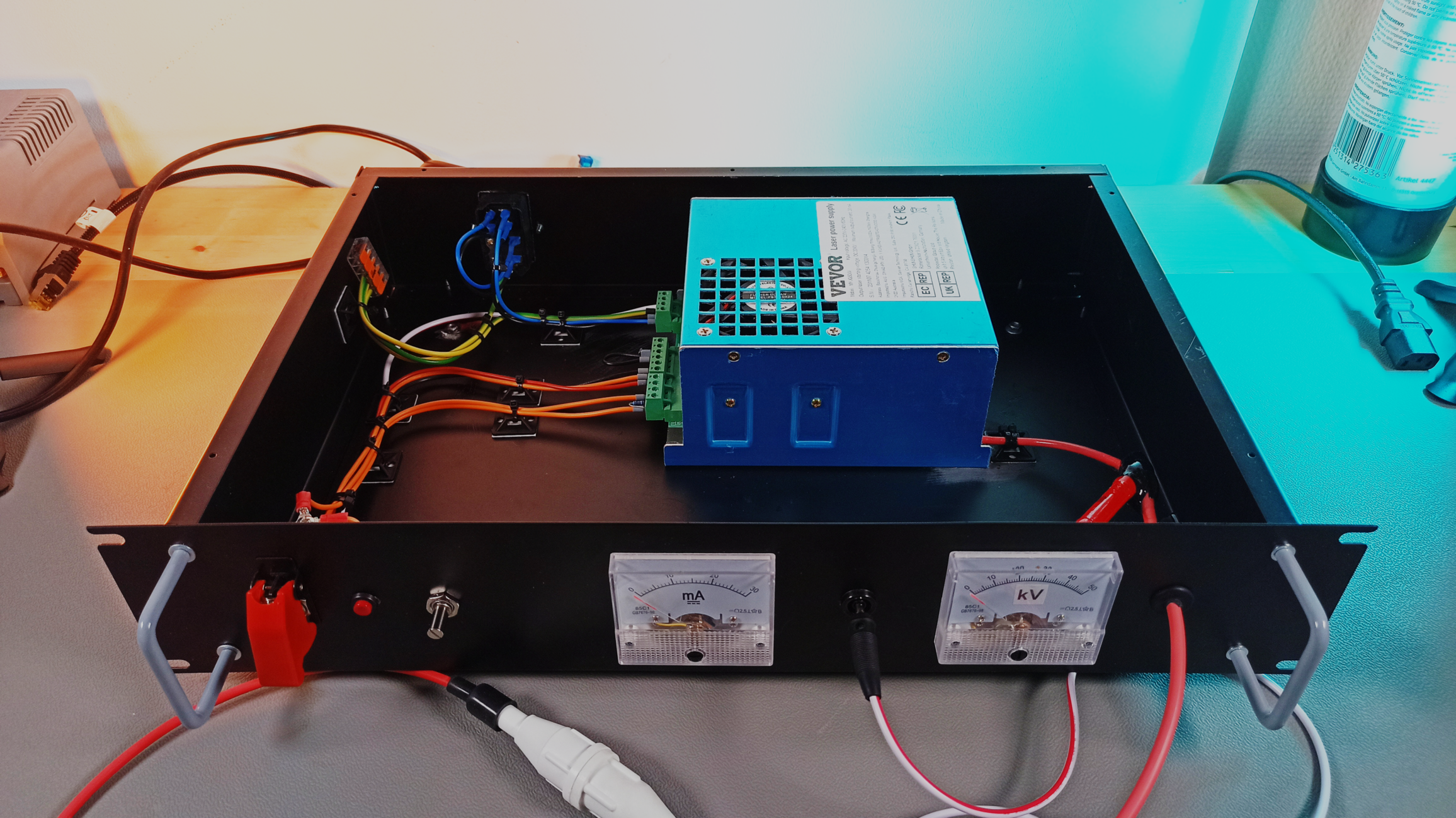
The entire project is mounted inside a 19" case. There is a (pretty fancy) single-pole, single-throw switch and a small momentary switch to enable the high-voltage output. A 10-turn potentiometer allows for easy adjustment of the desired output voltage. Current and voltmeters provide insight into the current operating parameters. To avoid having to find a panel mount high voltage connector, the high voltage cable (rated for up to 50 kV) was simply fed through a rubber grommet to the outside world. An inexpensive high voltage connector is then used to establish connections to future projects [3].
Top-view of the high-voltage power supply and its internal wiring around the VEVOR laser power supply
Current and Voltmeter
One primary design requirement is to have a voltmeter and a current meter to monitor voltage and current simultaneously. The current measurement is accomplished through a 30 mA panel meter. To stay clear of the high voltage itself, the current meter is installed so that the measurement occurs between the load and ground. Low side current sensing so to speak.
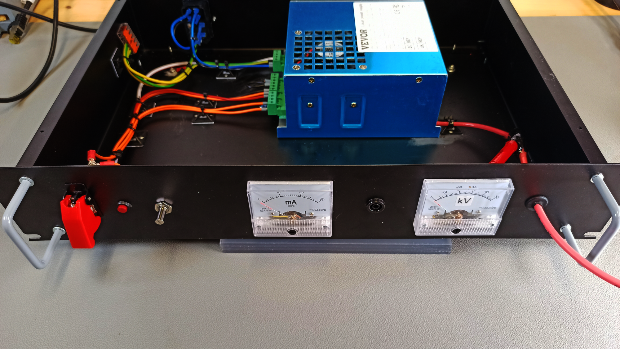
Front facing top-view of the high-voltage power supply and its internal wiring
A simple voltmeter would be quite easy to buy off the shelf for very little money, if it wasn’t necessary to measure up to 30 kV or possibly more. The simple, low-cost solution is to use a 50 µA current meter and a 1 Gigaohm resistor connected between the high voltage supply rail and ground. Following Ohm’s law (I = V/R), the current through a one Gigaohm resistor is conveniently 1 µA per kilovolt. So at 30 kV, the current meter schould indicate a current of 30 µA (Eq. 1).
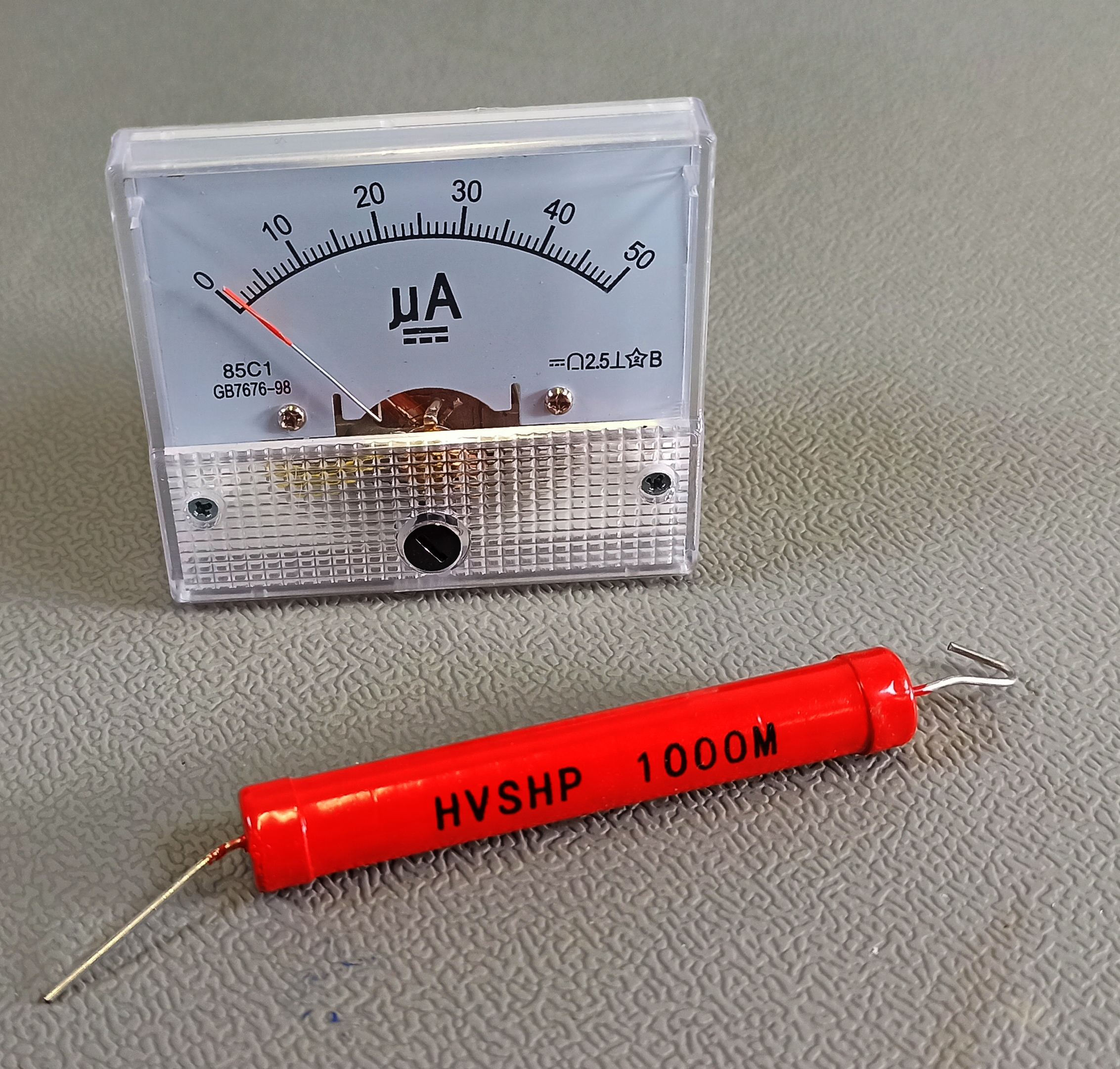
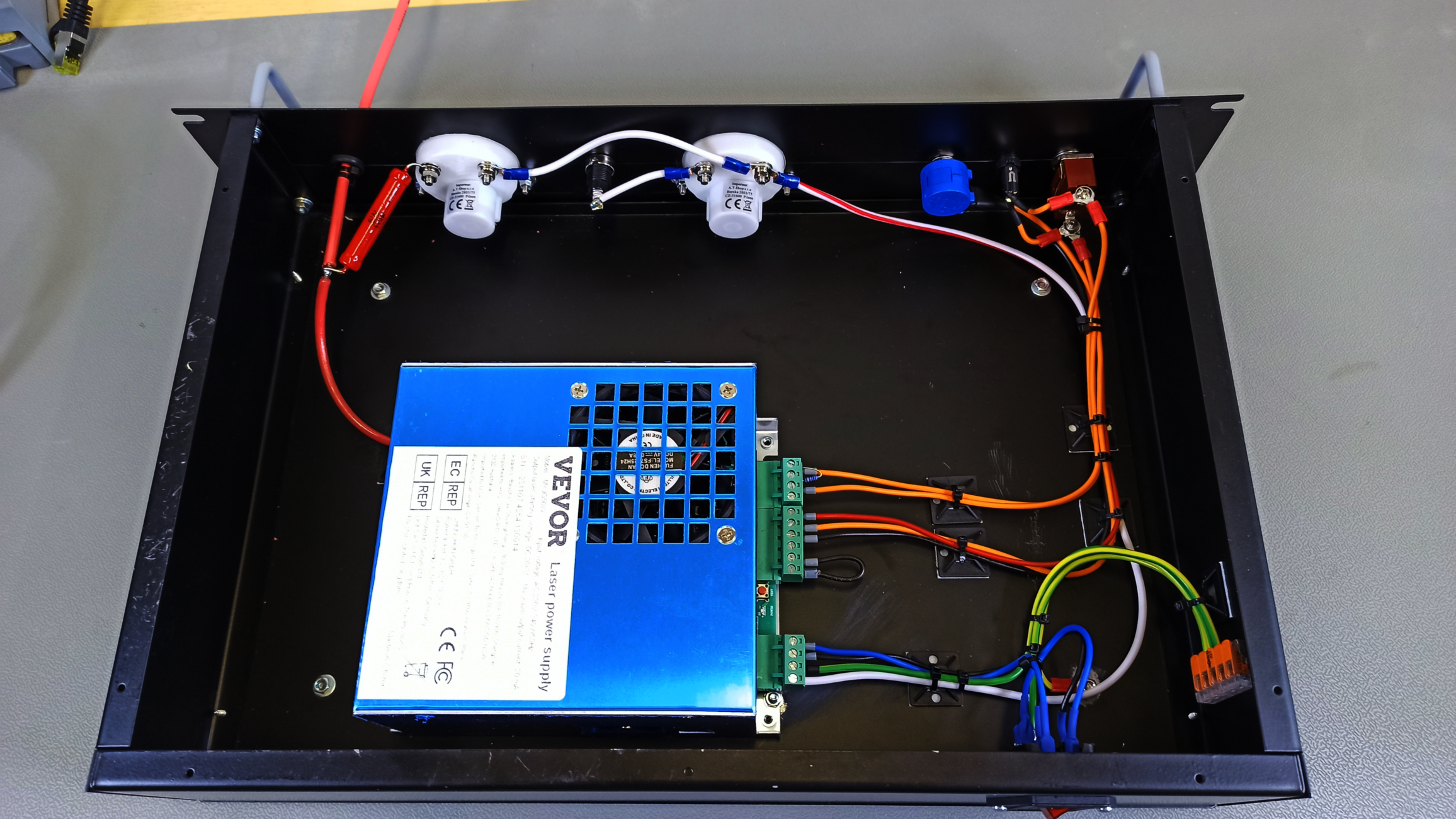
A 1 Gigaohm resistor and a 0 – 50 µA Ammeter suitable for measuring voltages up to 50 kV
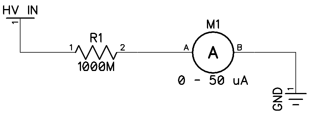
High voltage measurement set-up using a 1 Gigaohm resistor and a 0 to 50 μA ammeter
(1) 
(2) 
Careful readers might note that the current meter itself has an internal resistance and that, therefore, the real current is actually lower than expected. Thus the current meter’s indication should be lower than desired. While this is technically correct, with the meaurement resistor having a value of 1 Gigaohm, even a few hunded Kiloohms more make little to no difference. Equation 2 shows that even an extra 125 Kiloohms in series will still yield a result that is accurate to within two decimal places. Therefore, the meter’s internal resistance can be considered to be insignificant for this purpose. For the perfectionists out there, any resulting error can be trimmed out using the adjustment screw on the meter itself.
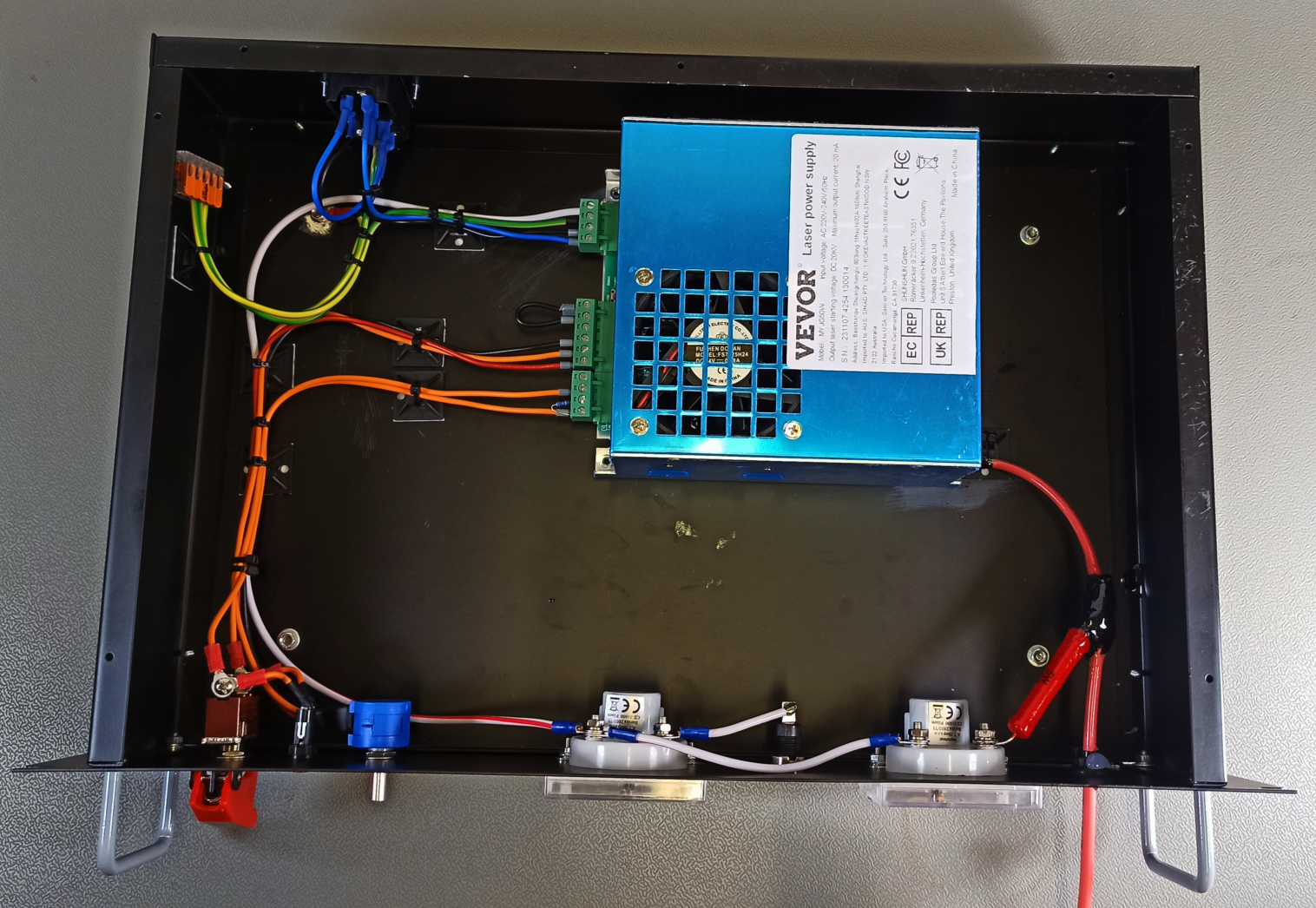
From left to right: High voltage output cable (red), 1 Gigaohms measurement Resistor, 50 µA current meter for voltage measurement through measurement resistor, ground connection and 30 mA current meter.
The solder junction between the high voltage output cable and the 1 Gigaohm measurement resistor poses a problem of its own; Usually, a bit of heat shrink tubing would be sufficient to prevent most exposed contacts from causing havoc. But not at a voltage of up to 30 kV. The solder joint is covered in multiple layers of MG Chemicals 4226A insulting varnish [2]. And while this varnish has an extremely high breakdown voltage of 3 kV per mil (= 0.0254mm), I am not stopping there. Several pieces of cloth are soaked in epoxy and carefully wrapped around the joint. This is quite literally a t-shirt cut up into little strips, soaked in epoxy. Somewhat peculiar but efficient.
Laser Supply Pinout & Control Wiring
Figuring out the pinout of the laser power supply took a bit of effort. While there was a manual included, it’s English and nomenclature was fairly questionable. With a bit of try and error (and an unintended laser discharge), I was able to figure out the proper pinout eventually.
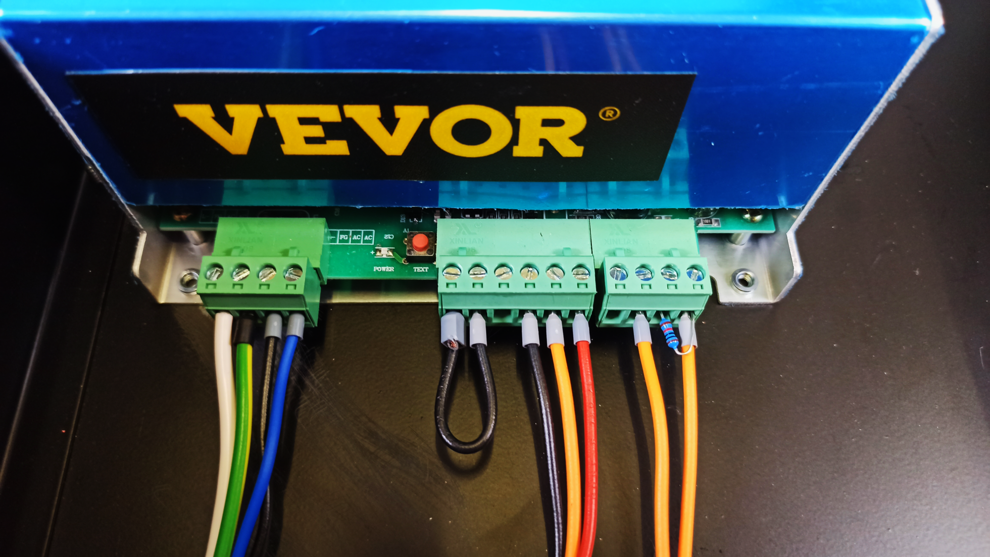
Connections to the commercial laser power supply: Mains voltage input (left connector), output voltage adjustment (center connector) and enable / disable input (right connector)
To make life easier for anyone following along at home, here is the correct pinout table for the connectors on the laser power supply:
Mains Connector (left):
Pin 1 (left) Pin 2 Pin 3 Pin 4 (right) Ground
(white)Mains Ground
(green/yellow)Mains Neutral
(blue)Mains Phase
(black)
Control Voltage Input Connector (center):
Pin 1 (left) Pin 2 Pin 3 Pin 4 Pin 5 Pin 6 (right) To Pin 2
(black)To Pin 1
(black)Not Connected Voltage adj. Ground
(black)Voltage Control Input
(orange)Voltage adj. 5 VDC
(red)
Enable / Disable Input Connector (right):
Pin 1 (left) Pin 2 Pin 3 Pin 4 (right) Not Connected GND Out
(Orange)5 V DC Out
(10K Resistor to Pin 4)Low-active input
(orange)
With the correct pinout figured out, the rest of the control wiring is pretty straight-foward. Mains power is fed into the casing through a switchable, fused IEC320 IEC60320 connector. The mains voltage is connected directly to the laser power supply. It should be mentioned that signal ground, high voltage ground and earth ground are connected internally inside of the laser supply. Just to be sure that there’s a proper connection to the metal frame of the 19" case, some of the paint is removed and a ring terminal with a dedicated ground wire is attached to the case. Additionally, the paint is also stripped below the laser supply before bolting it in place to ensure a good ground connection between the case and the supply itself.
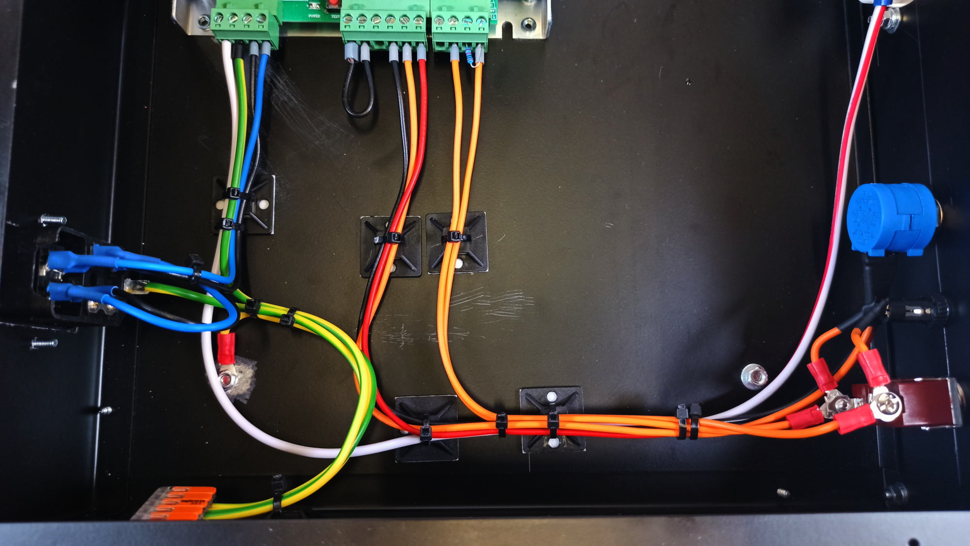
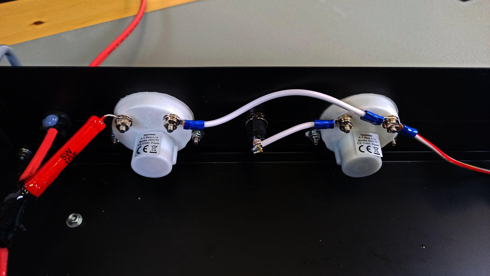
Close-up of the internal wiring: IEC320 mains voltage intput connector (left), VEVOR laser power supply connectors (top) , enable / disable switches and voltage adjustment potentiometer (right)
A 10-turn, 10 Kiloohms potentiometer is used to set the desired output voltage. The control voltage input of the laser power supply expects a control voltage between 0 to 5 Volts to adjust the output voltage from minimum to maximum. Conveniently, ground and 5 V DC terminals are provided directly next to the control voltage input. The latter is connected to the wiper of the potentiometer, ground and 5 Volts DC to the ends of the resistive strip. A single-pole, single-throw switch and a momentary switch for enabling the high voltage output are wired in parallel and connected between ground and the active-low enable input. Just to be on the safe side, I added a 10 Kiloohms pull-up resistor between the enable pin and 5 V DC.
Test Results
Let’s be honest, testing a high-voltage power supply is the most fun part of the entire build. But I wanted this moment to be special. Simply producing some arcs is kind of uninspired. So I quickly built a (sub-optimal) spark gap transmitter with an emission frequency of around 3 MHz. With the spark gap connected to the power supply, the mains voltage is finally connected to the high voltage power supply. Somewhat fearful of what might arc over, the momentary switch is pushed and after adjusting the output voltage to a sufficiently high level, the spark gap transmitter hapilly fired away.
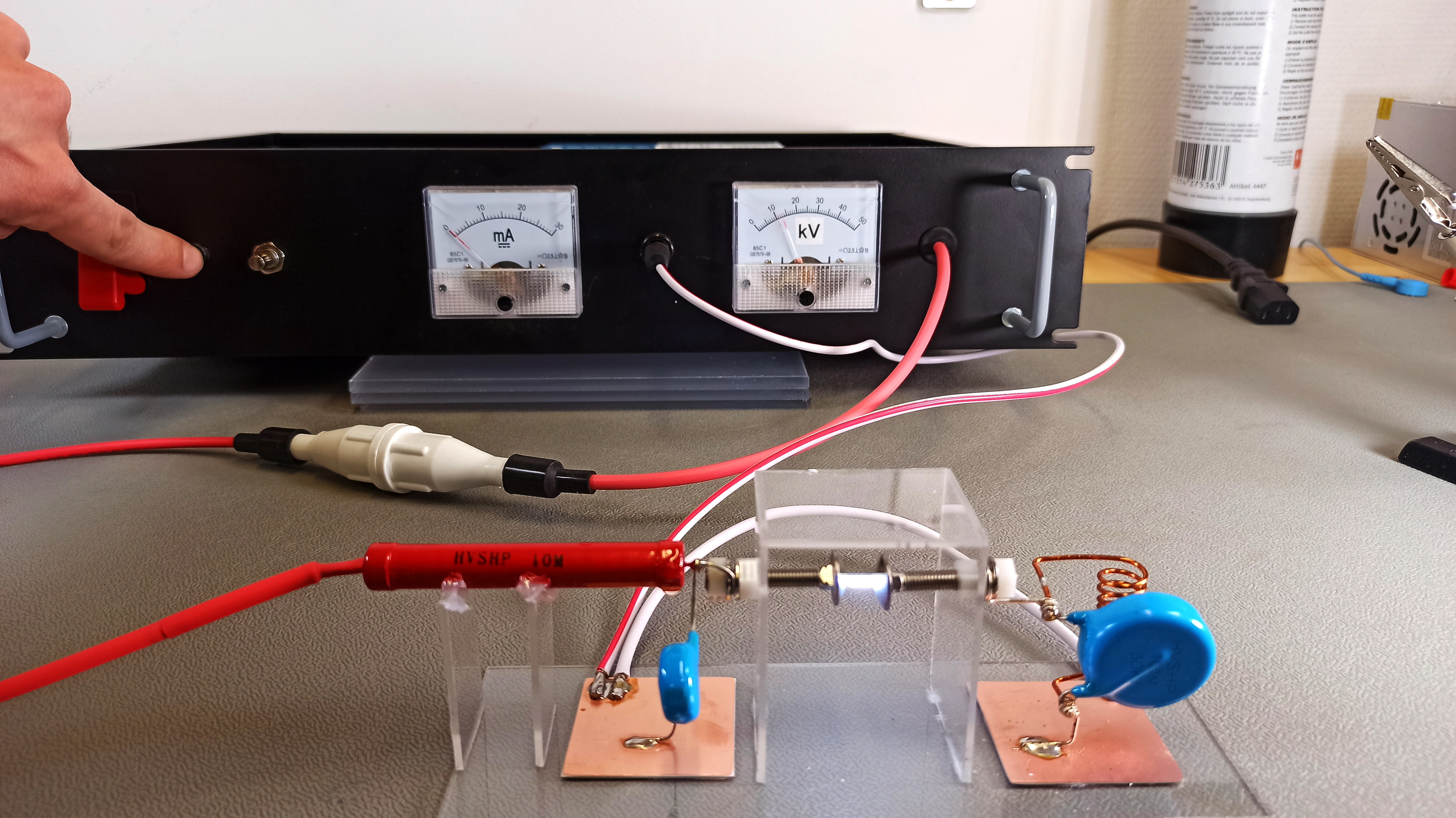
Spark-gap transmitter used for testing the high voltage power supply
Just as a teaser: The spark gap transmitter itself, including much better designs than the one shown here, will be the subject of an upcoming article. So stay tuned!
YouTube Video
Conclusion
My idea of combining commercial reliability and low-costs homebrewing is a complete success. The overall cost ist about 100 to 150 USD, depending on where exactly the components are sourced. This high voltage power supply will be the foundation of some interesting future content. I should add that there are commercial laser supplies that are capable of providing up to 50 kV output voltage with currents in excess of 30 mA. So if you need even higher voltages than the 30 KV shown in this article, that might be an avenue to explore. However, the higher voltage laser supplies are of course also more expensive. Still a lot less expensive than a commercial high voltage laboratory power supply.
Links and Sources:
[1] VEVOR 50W CO2 Laser Power Supply, Amazon: https://amazon.com/
[2] MG Chemicals 4226A, Dr. Dietrich Müller GmbH: https://www.muellerbestellung.de/
[3] MCWlaser High Voltage connectors, Amazon: https://amazon.com/
Westerhold, S. (2024), "DIY: Adjustable 30 kV High Voltage Power Supply". Baltic Lab High Frequency Projects Blog. ISSN (Online): 2751-8140., https://baltic-lab.com/2024/03/inexpensive-5-kv-to-30-kv-high-voltage-power-supply/, (accessed: July 26, 2026).

- Conducted Emissions on the Bench: Implementing the CISPR 25 Voltage Method - December 15, 2025
- WebP-Images without Plugin - January 14, 2025
- Firewall Rules with (dynamic) DNS Hostname - January 14, 2025
DIY Spark Gap Transmitter | Baltic Lab
[…] wire is soldered directly to the inductor’s tap. The input of the circuit is connected to my DIY high-voltage power supply. An XHDATA D-808 multi-band receiver, set to 2.995 MHz and Amplitude Modulation (AM), is utilized […]
NOEL RICE
Great video and article!
FYI: on the mains connector block, the pin 3 & pin 4 blue/black are reversed.
klsfjkldsj
Hello, great project. I wanted to make similar but I read about CO2 laser power supplies and it says that this kind of supply gives HV but it drops to much lower voltage after CO2 laser is ignited. Do you see this problem in your setup? Can you have more or less stable HV for for example 10 minutes? thanks for answer!
John
Next step would be to make it computer controllable. That would allow profiles to be run with precise timing. One of the features needed in my research.
Brody
What are the other dimensions of the case?
I’m assuming the 19in. is referring to the length. What is the height and width?
Sebastian Westerhold
The width is 19 inches, the height 3.5 inches and the depth 12 inches.
Brody
OK, thank you! I’m in the process of gathering supplies for it right now and am trying to decide whether to build the case myself from scrap sheet metal or buy it commercially lol.
On another note, how do you think one might go about making a device to transmit a ~300Hz. electromagnetic signal for the following application? The proposed application is discussed in this video at ~ 37:00 minutes:
https://youtu.be/z-pTERbyEsY?si=J2oDXjvLqe6R9igL
If you don’t have time to look into this that is completely understandable, I just thought it was an interesting idea…
mark
How has this held up to this point.
Any problems with the vevor supply?
Others say they will go bad being used with open circuit output.
Thanks
Sebastian Westerhold
So far I haven’t had any issues with it at all.