UPDATE: There also is a German version of this article available on my German blog: SITOR-B / NAVTEX Testsignal mit Arduino und Funktionsgenerator erzeugen
General Overview
Originally, I wanted to show how to repair a “NAV4 Navtex” NAVTEX receiver by ICS Electronics that’s been sitting in my junk box for a while now. But the repair turned out to be rather boring. After realigning the filters of the input stage, the receiver came back to life. During testing, another problem emerged though. NAVTEX stations transmit on a fixed schedule. Therefore, I had to wait for 4 hours between tests in order to wait for the next transmission from the Deutsche Wetterdienst (DWD). Since I had previously generated avionics related test signals (e.g. ILS Localizer / Glide Slope Test Signal Generation at home), I decided to dive into the maritime world of radio communication and try so find an easy way to generate valid NAVTEX signal myself.
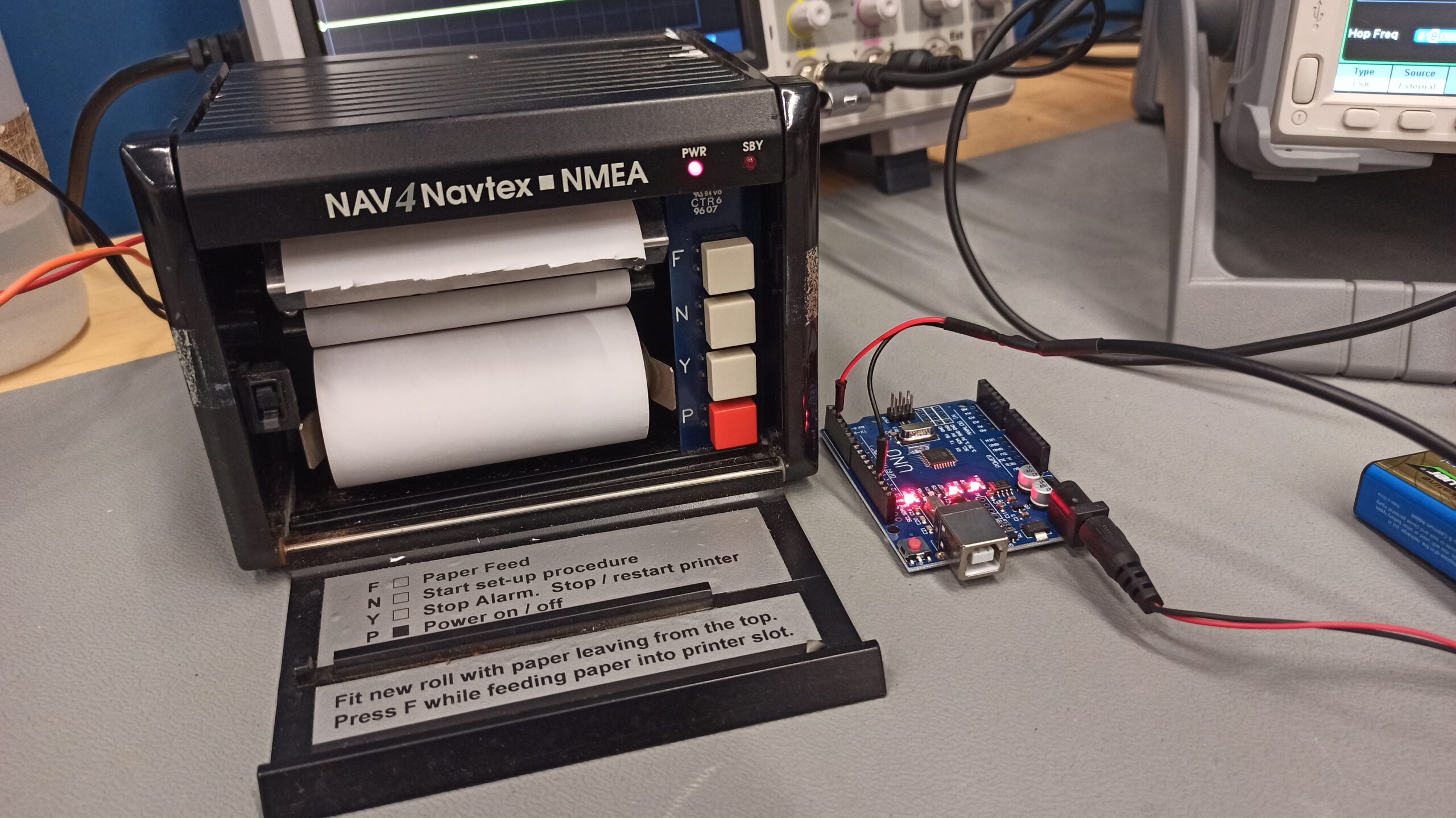
NAV4 Navtex by ICS Electronics
NAVTEX (NAVigational TEleX) is a radioteletype service used in the maritime world to distribute navigational and meteorological warnings and forecasts. Even though the system is quite old, the International Convention for the Safety of Life at Sea (SOLAS) still requires certein vessels to be equipped with NAVTEX receivers. The system transmits CCIR476 encoded characters at a rate of 100 baud on 518 Khz or 490 kHz using Frequency-shift keying (FSK). The NAVTEX message format is layered on top of SITOR (SImplex Teletype Over Radio) mode B. Since SITOR-B uses basic forward error correction (FEC), NAVTEX messages are somewhat robust to interference and in weak signal situations.
CCIR476 Character Encoding
CCIR476 is a 7-bit character encoding similar to 5-bit Baudot code. In a valid character, exactly 4 of the 7 bits are ‘1’. Therefore, it is possible to perform a basic error detection on the receiver side. CCIR476 encoding is used for SITOR and AMTOR (Amateur Teleprinting Over Radio) transmissions. AMTOR is basically just the amateur radio equivalent of SITOR. Since there are Arduino libraries for all kinds of amateur radio relatet protocols, I was very confident that there would be a CCIR476 encoding library. But I was wrong. That was bad news, because it meant more legwork for me. But there is good news for everyone who might want to use a CCIR476 encoding / decoding library as well: My CCIR476 library for Arduino [1] is now available through the Arduino library manager or directly from the GitHub repository [2].
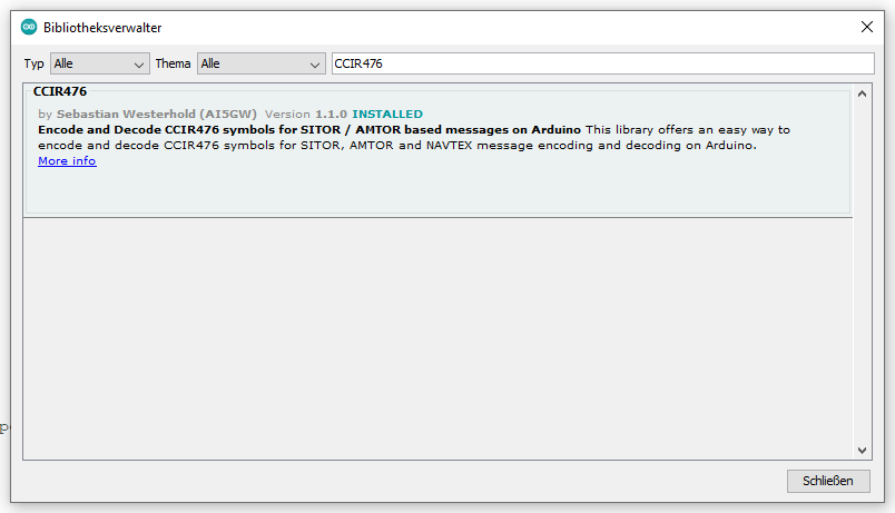
CCIR476 encoding / decoding library available from the Arduino library manager
CCIR476, just like Baudot code, uses two different character tables. One for letters and one for figures. Control characters are transmitted to switch between letters and figures mode. Having two look-up tables for ASCII characters and returning the corresponding CCIR476 character is an easy task. The library keeps track of whether or not the passed ASCII character is in the letters or figures table and provides a feedback function to detect mode changes in order to transmit the necessary control characters.
SITOR-B / NAVTEX Protocol
The International Telecommunication Union (ITU) is a good place to find specifications of communication protocols. On their website I found the ITU recommendation M.476-5 titled “Direct-printing telegraph equipment in the maritime mobile service” [3].
The TL;DR summary of the document comes down to two important points: Transmissions are initiated by sending the Phasing Signal 1 & 2 alternatingly. Every character is transmitted twice with 4 other characters in between. Transmissions are terminated by sending the phasing signal 1 three times in a row as “end of emission signal”.
The document describes the FEC implementation as follows:
“The station sending in the collective or in the selective B-mode (CBSS or SBSS) emits each character twice: the first transmission (DX) of a specific character is followed by the transmission of four other characters, after which the retransmission (RX) of the first character takes place, allowing for timediversity reception at 280 ms time space;“
Translated to the Arduino program, a transmit buffer was used to implement the FEC according to the specifications. The relevant code looks like this:
void SITOR_Transmit_FEC(byte SYM)
{
Transmit_SYMBOL(SYMBOL_BUFFER_1);
SYMBOL_BUFFER_1 = SYMBOL_BUFFER_2;
SYMBOL_BUFFER_2 = SYMBOL_BUFFER_3;
SYMBOL_BUFFER_3 = SYM;
Transmit_SYMBOL(SYMBOL_BUFFER_3);
}
Besides fulfilling the requirements of the SITOR-B protocol, there are also NAVTEX specific protocol demands. NAVTEX requires any message to be initiated by transmitting the characters “ZCZC” and to be terminated by the characters “NNNN”. After the initiating “ZCZC” characters, a 4-character “header” is transmitted. The header contains a transmitter identity character, a subject indicator character and two message serial number characters. My example code uses “SA00”, whereas “S” stands for the DWD transmitter in Pinneberg Germany, the “A” identifies the message as a navigational warning and the “00” is the serial number of the message.
Test Setup and Results
The example sketch was compiled and flashed to an Arduino Uno. When power is applied to the Arduino, it outputs a CCIR476 encoded bitstream using the SITOR-B / NAVTEX protocol at the correct rate of 100 baud on digital pin 2.
NAVTEX bitstream output on digital pin 2 of the Arduino
The bitstream from the Arduino Uno was then connected to the “Aux In/Out” connector of a Siglent 1032X function generator. The function generator was set to a frequency of 517.915 kHz. The inbuilt FSK modulation feature was enabled, the modulation source set to “External” and the FSK hop frequency set to 518.085 kHz.
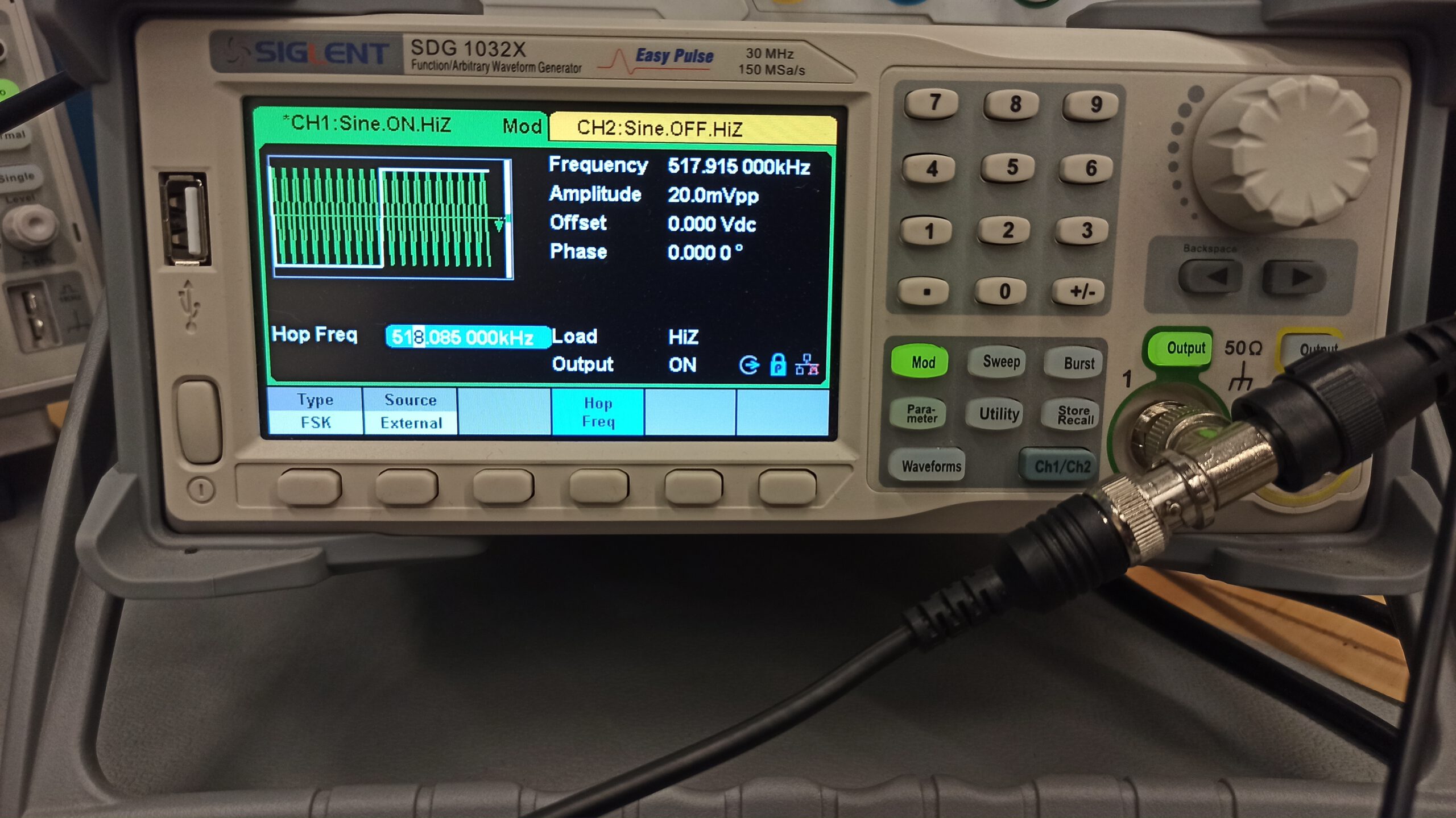
Siglent 1032X used as FSK modulator for SITOR-B / NAVTEX test signal generation
After resetting the Arduino Uno it didn’t take long until the “SBY” LED of the Navtex receiver started blinking. Shortly afterwards, the thermal printer of the receiver came to life and printed the transmitted test message without errors.
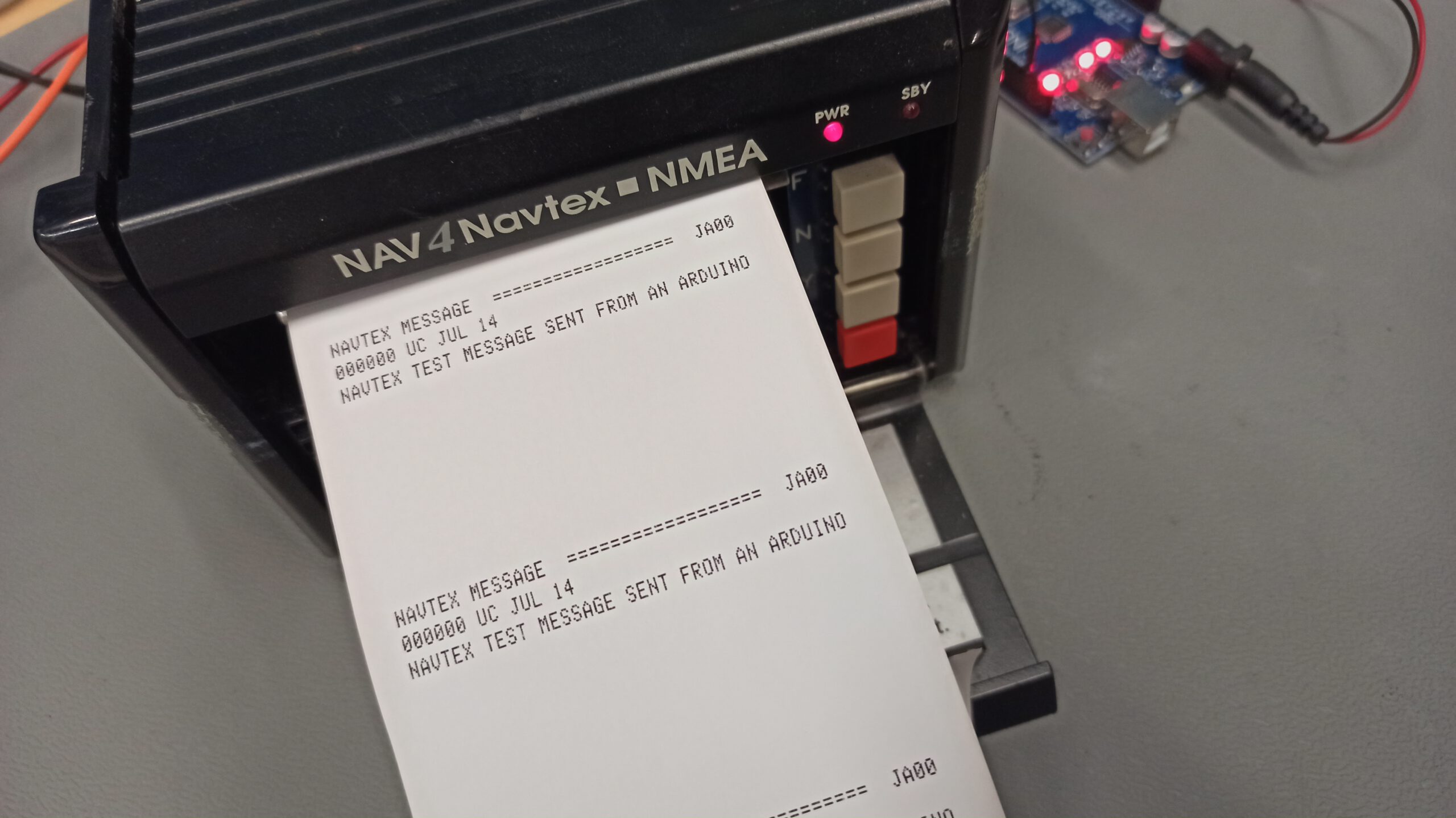
The NAVTEX test signal was successfully received on a NAV4 Navtex receiver
Bonus Material
Even though FSK modulation functionality is fairly standard on modern function generators, a SI5351A clock generator breakout board was also tested successfully for the 518 kHz FSK signal generation. The source code for the SI5351A based version is also included in the CCIR476 library example folder. It can also be found here.
There also is a short video of the test setup. And yes, the video was recorded with a potato, so enjoy:
Conclusions
This project proves that sometimes it is quite educating to invest several days of work in order to avoid waiting for 4 hours. If I would have just waited the 4 hours, I wouldn’t have learned much about CCIR476, SITOR-B and NAVTEX. Neither would I have learned about the process of writing and submitting own libraries to the Arduino library index. Sometimes impatience leads down very interesting roads.
Maybe this project will inspire some people to conduct their own SITOR-B or AMTOR experiments. Or at least inspire to experiment with using a simple Arduino as bitstream generator for test signal generation in general.
Links and Sources:
[1] CCIR476 Arduino library, GitHub: https://github.com/AI5GW/CCIR476
[2] CCIR476 Arduino library, arduino.cc: https://www.arduino.cc/
[3] ITU recommendation M.476-5, ITU: https://www.itu.int/
Westerhold, S. (2022), "SITOR-B / NAVTEX Test Signal Generation". Baltic Lab High Frequency Projects Blog. ISSN (Online): 2751-8140., https://baltic-lab.com/2022/07/sitor-b-navtex-test-signal-generation/, (accessed: March 26, 2026).

- Conducted Emissions on the Bench: Implementing the CISPR 25 Voltage Method - December 15, 2025
- WebP-Images without Plugin - January 14, 2025
- Firewall Rules with (dynamic) DNS Hostname - January 14, 2025
Impatience Is A Virtue When Testing This Old Maritime Teleprinter | Hackaday
[…] certainly came into play for [Sebastian (AI5GW)] while hacking a NAVTEX receiver. The NAVTEX system allows ships at sea to receive text broadcast alerts for things like changes in […]
Victor
Hello! May I ask You for some comments for this project?
Interested – is there binary output? Is it possible to do FSK without modulation – with 1700Hz center freq?
Sebastian
Hey Victor! Yes, the Arduino also outputs the FSK-Data in binary format on one of the pins. The shift frequency can be adjusted freely in the software. I use an SI5351A for the RF generation so it is possible to operate up to about 160 Mhz.
Jay
Hello, nice work. Somebody asked me to repair a nav5 receiver, but how to test it? My rf generator had no sweep function so i built one with whatever rf function i could think of, esp32 with touch screen. I found your code and incidently i have an si5351 in my generator so i added a navtex send function. No luck…i fixed what was defective and could trace the fsk upto the cpu, what i usually do is to go back to the basics, i took a nano board and another si board and that worked, changed the nano by an esp32, that worked too…connected the si to the wiring in my generator, worked..replaced the si module and presto it worked, not sure why because the si module was working fine, maybe more jitter on the xtall, i bought it a few years ago and recently bought a few more and those work with the navtex code. Anyway i could demonstrate the nav5 is fixed and working so the man was very happy. Thanks for sharing the code.
Gerald
Great project and very interesting read. Thanks for sharing.
73 de VE4ACE
Sebastian
Glad you liked it! 73s DE AI5GW
Masao@FAL
Thank you for presenting the excellent NAVTEX signal generation program.
I was relieved of the four-hour wait.
I used si5351 to make it work.
I am developing a direct conversion NAVTEX receiver consisting of a CMOS4069UB chip.
We implemented LOCAL, MIX, AMP, and LPF using one 4069UB.
Sönke Brix
Hi Masao,
your concept sounds very interesting! Are you willing to share some ideas and some details – that would be great!
And thanks so much to you Sebastian, your post saved so much time during my Navtex repair attemps 😉
Greetings