The easiest way to implement distortion through a DSP algorithm would be hard clipping. With this method any value above a certain threshold will be fixed to that threshold level. While this is absolutely possible, hard clipping sounds very harsh. This might be desirable for some metal fans but it doesn’t mimic the behaviour of tube or diode distortion circuits in which the clipping process is a lot more gradual.
Update (08/21/2023): A YouTube video titled “Overdrive and Distortion Effect Digital Signal Processing (DSP) Algorithms on the Arduino GIGA R1” is now available.
Modelling Clipging Mathematically
The Shockley ideal diode equation is a good starting point to model the behaviour of semiconductor diodes. It descibes the current through a diode as a function of the applied voltage. In order to develop a suitable DSP algorithm, however, an equation describing the output voltage as a function of input voltage is needed. There are many different equations approximating diode clipping circulating around the web and in professional literature [1], albeit not always without errors.
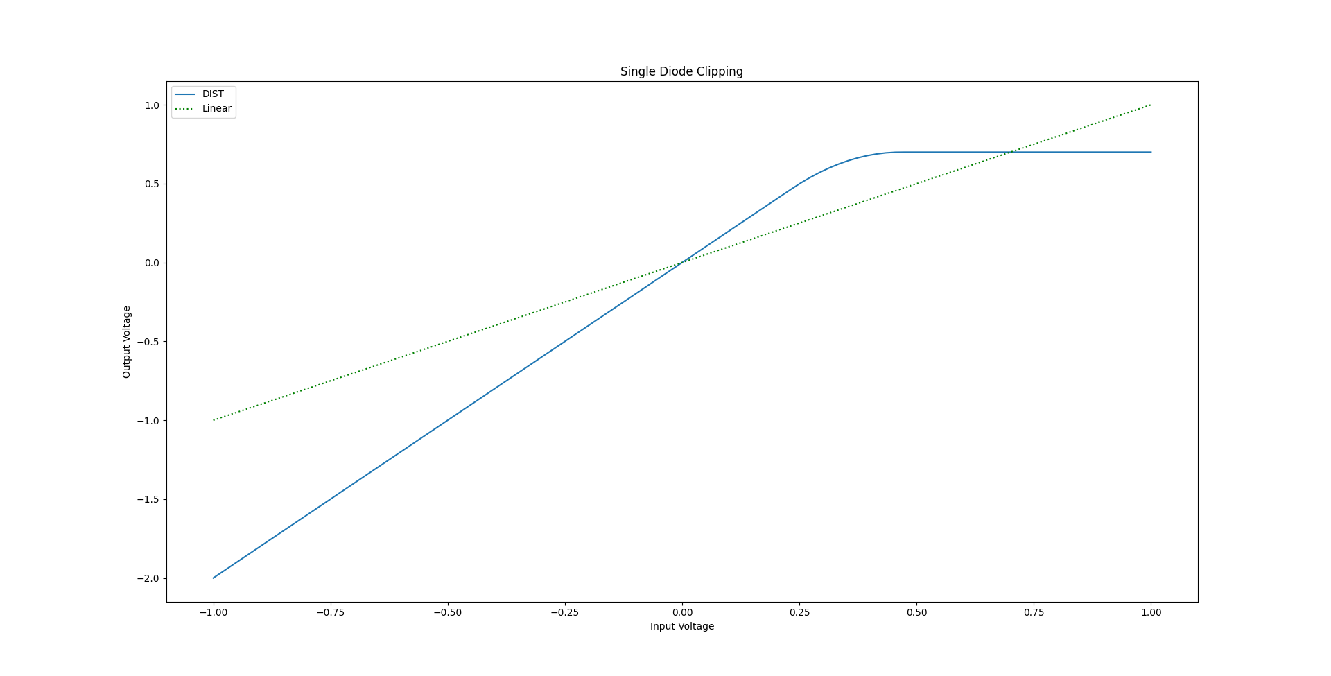
Single diode clipping step-function with output voltage as a function of input voltage shown (blue)
A simple approximation for diode clipping through a step function is shown in equation 1 (positive clipping) and 2 (negative clipping). The equation consists out of a linear part, a quadratic part and a hard-clipping part. Which one of the terms is shaping the output signal is determined by the input voltage.
(1) 
(2) 
Both equations were combined and plotted in Python to simulate dual diode clipping as it is often found in guitar distortion pedals:
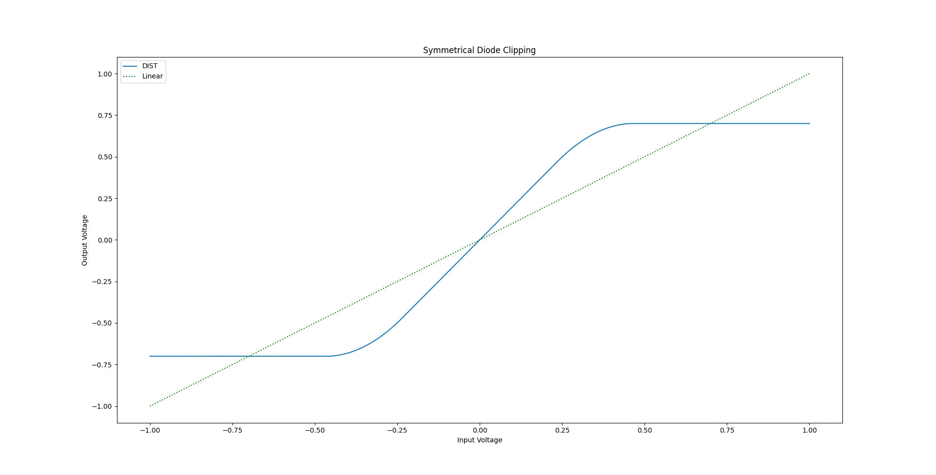
Dual, symmetrical diode clipping step-function with output voltage as a function of input voltage shown (blue)
Admittedly the easiest model that can be implemented in software is using only the hyperbolic tangent function (Eq. 3). Use of this function results in an even softer clipping at the top-end of the input voltage range.
(3) 
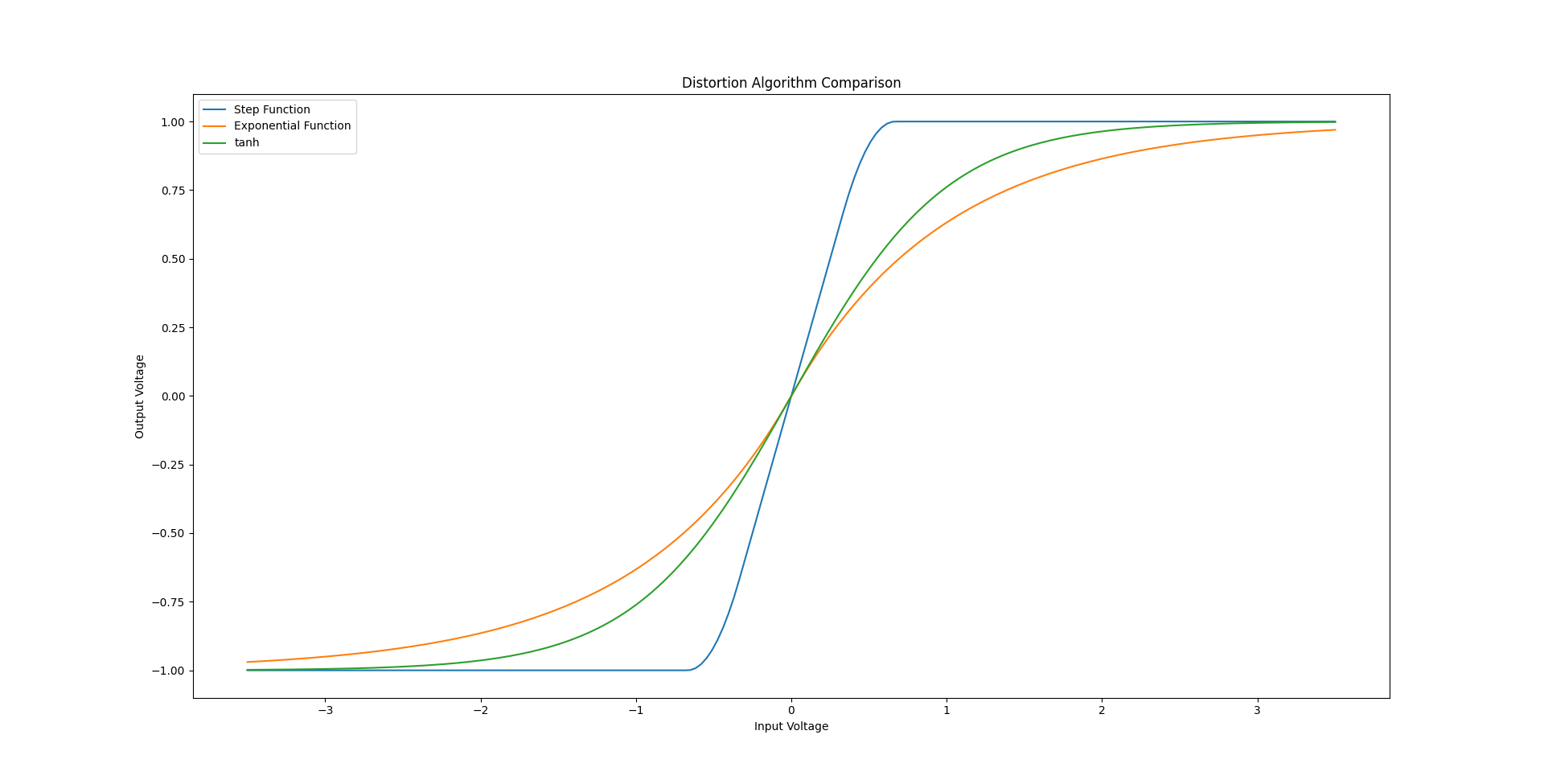
Output voltages for the different clipping equations as a function of input voltage. Step-function (Blue), exponential function (orange) and hyperbolic tangens (green)
The Schockley ideal diode equation is a natural exponential function. Therefore, it would make sense that a mathematical approximation would also be an exponential function with Euler’s number being raised to some variable. There is one particular function found in [1] that circulates around the web. The original equation contains a significant sign-error. Only the corrected version of the equation (Eq. 4) is shown here.
(4) 
(5) 
But even in the corrected form shown above (Eq. 4), the equation is still not suitable for direct implementation into a DSP algorithm just yet. The problem is the way the original author implements the signum function, which returns only the sign (+ or -) of a value. The  and
and  terms are supposed to switch the signs of operands depending on whether the input is positive or negative. This works very well until an input value is 0, because the function’s domain is limited to all non-zero values (Eq. 5). We can do better than that and transform the exponential equation from the book (Eq. 4) into another step-function (Eq. 6). Doing this actually also improves the computational resources required.
(6) 
The following graph simulates the resulting output voltage waveform for a sinusoidal 2 Vpp signal applied to the input of each of the algorithms shown here.
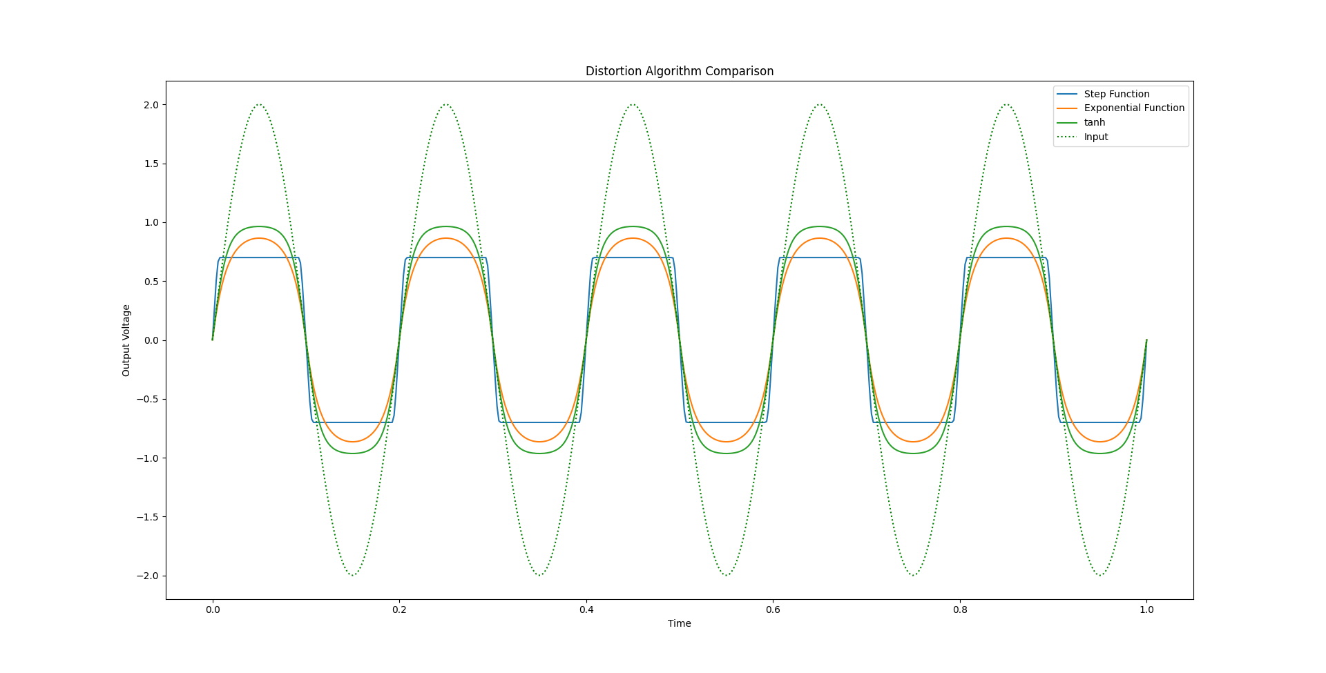
Time-domain simulation of output voltages for the different clipping equations as a function of time with a 2 Vpp sinusoidal signal applied. Step-function (Blue), exponential function (orange) and hyperbolic tangens (green)
Test and Results
With the math out of the way, the rest is fairly easy. For this experiment, the new Arduino GIGA R1 WiFi [2] has been used as it has two inbuilt DACs that come in handy for trying out the developed algorithms. The framework used here is derived from my Arduino GIGA R1 WiFi | Audio Loopback Example. The entire sketch can be found in the section at the end of the article.
For my first experiment, I implemented the step-functions (Eq. 1 and 2) for a dual diode, symetrical type of distortion. The results are quite satisfying.
Output (yellow) and input (purple) voltages of the step-function clipping algorithm implementet with an Arduino
Next, I made use of the two DACs of the Arduino GIGA R1 WiFi by applying different overdrive / distortion algorithms to the output of each DAC. The first channel utilizes the step-function (Eq. 1 and 2), the second the re-packaged natural exponent step function (Eq. 6). The results for various input voltage levels are shown in the following images.
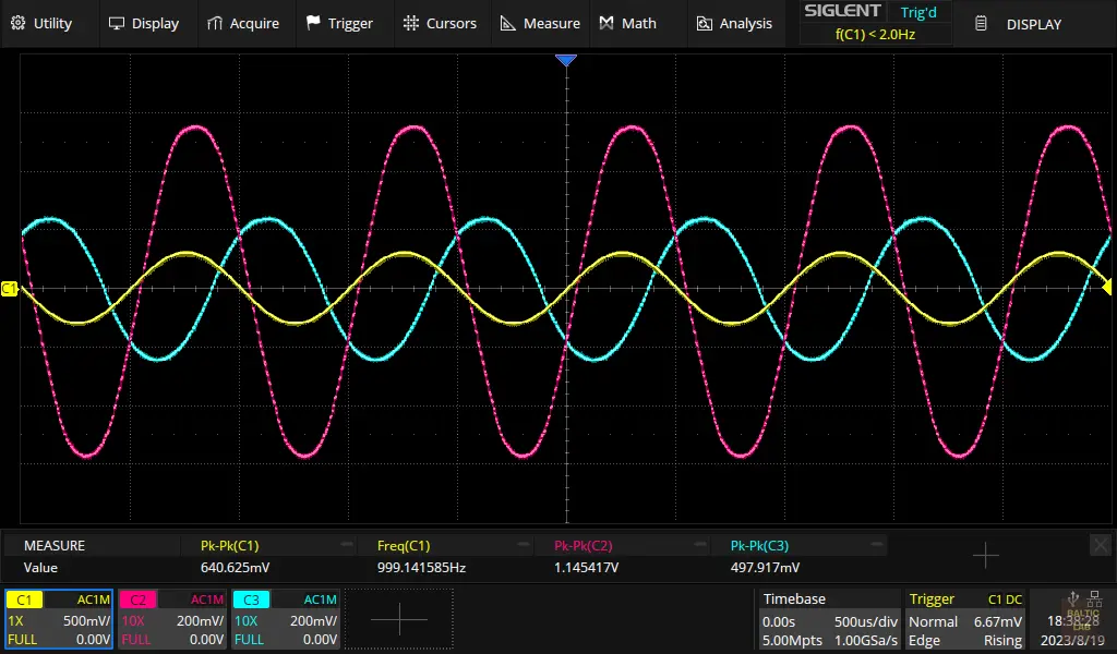
Input voltage (yellow), dual-diode step-function output from DAC0 (purple) and exponential function output from DAC1 (green) just before clipping.
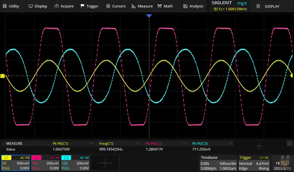
Input voltage (yellow), dual-diode step-function output from DAC0 (purple) and exponential function output from DAC1 (green) with clipping activity becoming visible.
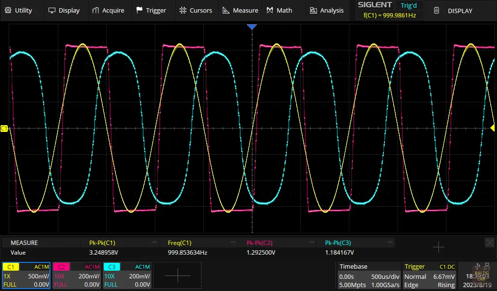
Input voltage (yellow), dual-diode step-function output from DAC0 (purple) and exponential function output from DAC1 (green) with strongly visible clipping.
Caution: Aliasing
Due to the nature of distortion, higher order harmonics of the input signal’s frequency will be present in the signal after applying distortion algorithms. All hormonics that exceed the Nyquist-limit (half the sample-rate) will inadvertently cause aliasing. Therefore, in a practical high-quality digital signal processing application, the sampled input signal would be upsampled first, the algorithm would be applied, followed by an anti-aliasing filter before downsampling back to the original sampling rate (or any other desired rate for the DAC). For this very simple example I omitted this step. Given the relatively high sample rate of 96 kS/s, the Nyquist limit is 48 kHz and thus relatively far away from the high-spectral density part of the usual guitar harmonics. However, this issue should be something to be aware of when implementing the alogrithm shown here in own designs.
Conclusions
It is absolutely possible to model different diode clipping behaviours and easily package the resulting equations into a DSP algorithm. Given the relatively low computational power needed, even a lower-end Arduino is perfectly capable of performing this task, allowing for software adjustable parameterization of the exact overdrive and distortion characteristics.
Arduino Sketch
/** Arduino Giga R1 WiFi - DSP Diode Clipping Example** Copyright (C) 2023 Westerhold, S. (AI5GW)* Web (EN): https://baltic-lab.com* ORCID: https://orcid.org/0000-0001-7965-3140** Tested sample-rates: 192000, 96000, 48000, 44100** This program is free software: you can redistribute it and/or modify* it under the terms of the GNU General Public License as published by* the Free Software Foundation, either version 3 of the License, or* (at your option) any later version.*/#include <Arduino_AdvancedAnalog.h>// Instantiate ADC 0 (Pin A0), DAC 0 (Pin A12) and DAC 1 (Pin A13)AdvancedADC Chan1(A0);AdvancedDAC Out1(A12);AdvancedDAC Out2(A13);// Define ADC Midpoint#define ADC_MIDPOINT 2047void setup() {// Set-up ADC0, stop program on failure// Resolution, sample rate, number of samples per channel, queue depth.if (!Chan1.begin(AN_RESOLUTION_12, 96000, 32, 32)) {Serial.println("ADC fail...");while (1);}// Set-up DAC0, stop program on failure// Resolution, sample rate, number of samples per channel, queue depth.if (!Out1.begin(AN_RESOLUTION_12, 96000, 32, 32)) {Serial.println("Failed to initialize DAC 1");while (1);}// Set-up DAC1, stop program on failure// Resolution, sample rate, number of samples per channel, queue depth.if (!Out2.begin(AN_RESOLUTION_12, 96000, 32, 32)) {Serial.println("Failed to initialize DAC 1");while (1);}}void loop() {if (Chan1.available()) {// Get handle for the input bufferSampleBuffer inBuf = Chan1.read();// Get handle for the output bufferSampleBuffer outBuf1 = Out1.dequeue();SampleBuffer outBuf2 = Out2.dequeue();for (int i = 0; i < inBuf.size(); i++) {// Dual diode, symmetrical clipping step-function on DAC0outBuf1.data()[i] = DiodeClippingStep(inBuf[i] - ADC_MIDPOINT, 800) + ADC_MIDPOINT;// Dual diode, symmetrical clipping exponential-function on DAC1outBuf2.data()[i] = DiodeClippingExponential(inBuf[i] - ADC_MIDPOINT, 800) + ADC_MIDPOINT;}// Write contents of the output buffer to the DACsOut1.write(outBuf1);Out2.write(outBuf2);// Release the input bufferinBuf.release();}}int DiodeClippingStep(int INPUT, int THRESHOLD) {float IN, OUT;int BUF = INPUT; // Store for sign revovery// Normalize input to threshold level = 1.0IN = (float)abs(INPUT) / THRESHOLD;if (IN <= (1.0 / 3.0)) {OUT = 2 * IN;} else if (IN <= (2.0 / 3.0)) {OUT = (-3.0 * (float)pow(IN, 2)) + (4.0 * IN) - (1.0 / 3.0);} else {OUT = 1;}// Undo NormalizationOUT = OUT * THRESHOLD;// recover signif (BUF <= 0) { OUT = -1.0 * OUT; }return round(OUT);}int DiodeClippingExponential(int INPUT, int THRESHOLD) {float IN, OUT;// Normalize input to threshold level = 1.0IN = (float)INPUT / THRESHOLD;if (IN < 0) {OUT = -1.0 + exp(IN);} else if (IN > 0) {OUT = 1.0 - exp(-IN);} else {OUT = 0;}// Undo NormalizationOUT = OUT * THRESHOLD;return round(OUT);}
Links and Sources:
[1] Zölzer, Udo. (2011). DAFX: Digital Audio Effects: Second Edition. 10.1002/9781119991298. : https://www.researchgate.net/
[2] Arduino Giga R1 WiFi, Elektorstore: https://www.elektor.com/arduino-giga-r1-wifi
[3] Westerhold, S. (2023), "Arduino GIGA R1 WiFi | Audio Loopback Example". Baltic Lab High Frequency Projects Blog. ISSN (Online): 2751-8140.: https://baltic-lab.com/
[4] Yeh, David & Smith, Julius. (2008). Simulating guitar distortion circuits using wave digital and nonlinear state-Space formulations. Proceedings - 11th International Conference on Digital Audio Effects, DAFx 2008: https://www.researchgate.net/
Westerhold, S. (2023), "DSP Diode Clipping Algorithm for Overdrive and Distortion Effects". Baltic Lab High Frequency Projects Blog. ISSN (Online): 2751-8140., https://baltic-lab.com/2023/08/dsp-diode-clipping-algorithm-for-overdrive-and-distortion-effects/, (accessed: May 28, 2026).

- Conducted Emissions on the Bench: Implementing the CISPR 25 Voltage Method - December 15, 2025
- WebP-Images without Plugin - January 14, 2025
- Firewall Rules with (dynamic) DNS Hostname - January 14, 2025
Tom
I found your post very useful for a question I had programming DAC0 and DAC1 on Arduino Giga R1 wifi. I want to create two unique sample buffers to drive the two DACs. The Arduino examples for AdvancedAnalog DAC programming got me close, but you provided the missing pieces. Thanks. I just got the Giga to play with in retirement. Cheers.
Sebastian Westerhold
Hi Tom, thank you so much for your kind words! I’m glad the post was helpful and that it provided the missing pieces for your project. Wishing you all the best with your projects – happy coding! Cheers!
Brian
What about distortion effect using an opamp clipping gain stage, such as what Tech21 did with their SansAmp GT2 pedal and PSA-1 DAW plugin.