After showing how to implement an Audio Loopback Device and a DSP Diode Clipping Algorithm for Overdrive and Distortion Effects on the Arduino GIGA R1 WiFi, this article will show how to implement a tremolo effect in software.
The Tremolo Effect
The tremolo effect has 2 basic parameters: Depth and Frequency. The depth determines how much the incoming audio signal is being altered by the effect and inversely how much of the original signal is passed-through unaltered. The frequency determines the frequency of a low-frequency oscillator. Another common effect parameter is the waveform itself. Sinusoidal, triangle and rectangle LFO waveforms are common.
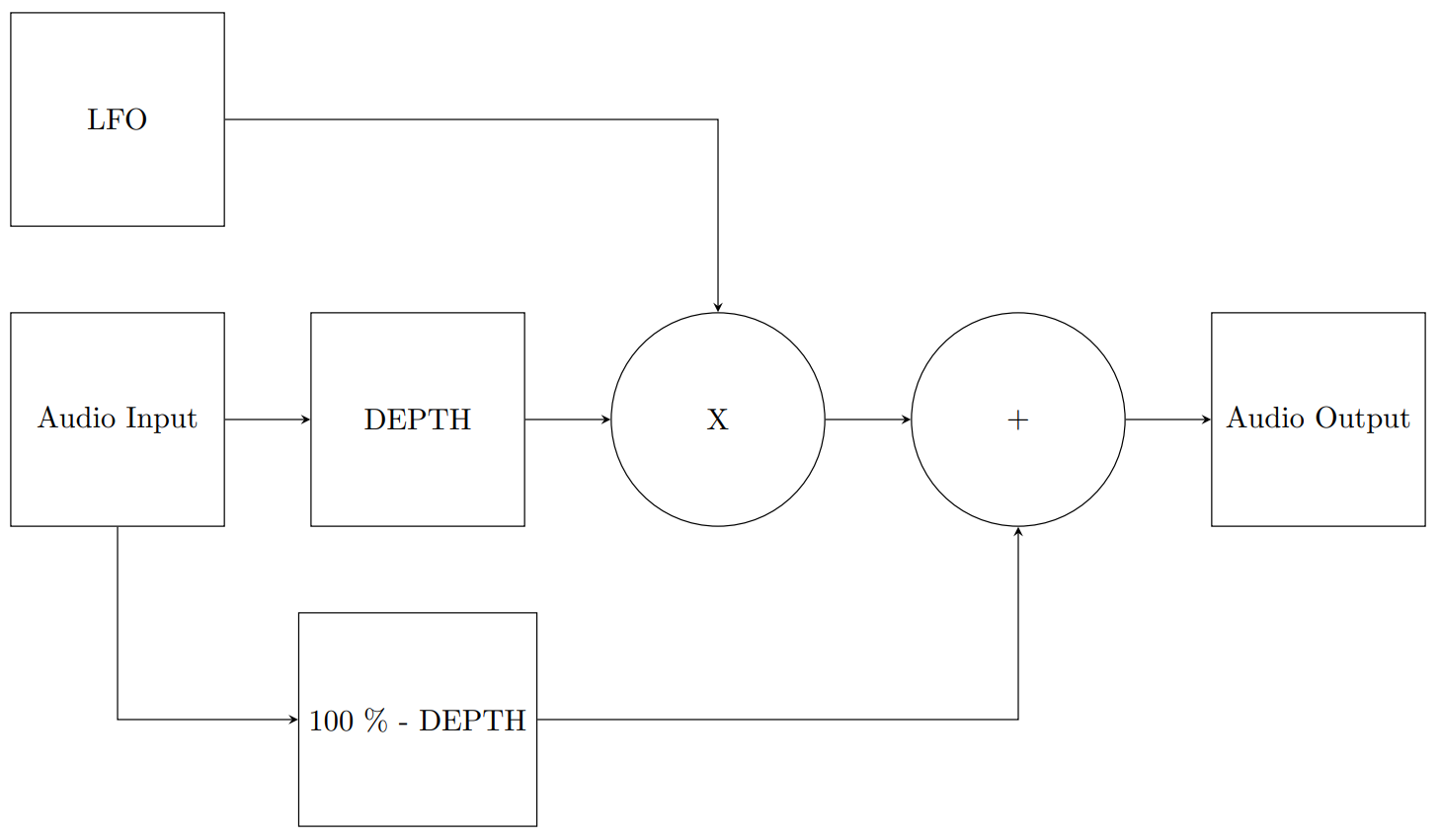
Block Diagram of a Tremolo Effect
The LFO produces a waveform at the pre-selected frequency. A portion of the incoming audio signal (or all) corresponding to the set depth-amount is then multiplied by the LFO signal, shaping it’s waveform envelope. The resulting signal is then added back together with the desired portion (or none) of the unaltered, original signal. And that’s all there is to the tremolo effect.
Software Implementation
The main loop of the program continiously acquires samples from the ADC0 input at a fixed sample-rate with the help of the AdvancedAnalog-library. Whenever the sample buffer is full, the samples get passed to an effect stack-function. The function first applies a DSP distortion algorithm and then passes the sample on to the tremolo function itself.
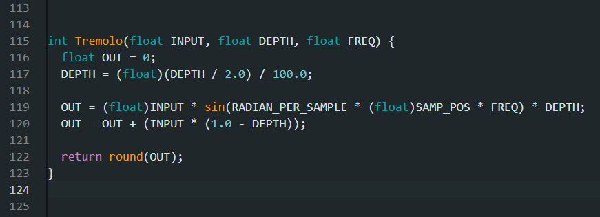
Tremolo effect implemented in an Arduino sketch
A global variable keeps track where the acquisition currently is located in time, relative to the sample-rate. MY example code only implements a sinusoidal waveform. Since the DSP alorithm operates in discrete-time and not continuous time, a variable holding the amount of radians per sample has been pre-calculated. The input sample is then multiplied by the sine value of the given frequency at the given sampling time. The resulting value is further multiplied by the fractional depth value. The result is then added to a fration of the original signal with the inverse amount of depth.
And this is what the end result sounds like (99 % modulation depth, LFO frequency = 5 Hz):
Conclusions
The tremolo effect is extremely simple to implement in software. As expected, the Arduino GIGA R1 is perfectly up to the task and even more than capable of stacking multiple effects for well-sounding results.
Arduino Sketch
The following sketch was tested on an Arduino GIGA R1 with various sample rates. Please note that the ADC is only able to capture positive voltages and may even be destroyed when applying a negative signal. Therefore, the input audio signal has to be shifted up before connecting it to the ADC0 input pin. A simple 10K / 10K voltage divider at the ADC input between the 3.3 V supply rail and ground will suffice for basic experiments.
/** Arduino Giga R1 WiFi - DSP Tremolo Effect Example** Copyright (C) 2022 Westerhold, S. (AI5GW)* Web (EN): https://baltic-lab.com* ORCID: https://orcid.org/0000-0001-7965-3140** Tested sample-rates: 192000, 96000, 48000, 44100** This program is free software: you can redistribute it and/or modify* it under the terms of the GNU General Public License as published by* the Free Software Foundation, either version 3 of the License, or* (at your option) any later version.*/#include <Arduino_AdvancedAnalog.h>// Instantiate ADC 0 (Pin A0), DAC 0 (Pin A12) and DAC 1 (Pin A13)AdvancedADC Chan1(A0);AdvancedDAC Out1(A12);AdvancedDAC Out2(A13);// Define ADC Midpoint#define ADC_MIDPOINT 2038#define SAMPLE_RATE 96000static float RADIAN_PER_SAMPLE = (float)(2.0 * PI) / SAMPLE_RATE;long SAMP_POS = 0;void setup() {Serial.begin(115200);// Set-up ADC0, stop program on failure// Resolution, sample rate, number of samples per channel, queue depth.if (!Chan1.begin(AN_RESOLUTION_12, SAMPLE_RATE, 128, 128)) {Serial.println("ADC fail...");while (1);}// Set-up DAC0, stop program on failure// Resolution, sample rate, number of samples per channel, queue depth.if (!Out1.begin(AN_RESOLUTION_12, SAMPLE_RATE, 128, 128)) {Serial.println("Failed to initialize DAC 1");while (1);}// Set-up DAC1, stop program on failure// Resolution, sample rate, number of samples per channel, queue depth.if (!Out2.begin(AN_RESOLUTION_12, SAMPLE_RATE, 128, 128)) {Serial.println("Failed to initialize DAC 1");while (1);}}void loop() {if (Chan1.available()) {// Get handle for the input bufferSampleBuffer inBuf = Chan1.read();// Get handle for the output bufferSampleBuffer outBuf1 = Out1.dequeue();SampleBuffer outBuf2 = Out2.dequeue();for (int i = 0; i < inBuf.size(); i++) {// Store buffer valueint INVal = inBuf[i];// Write copy to DAC0 output bufferoutBuf1.data()[i] = INVal;// Send value to the effect stack and write result to DAC1 bufferoutBuf2.data()[i] = EffectStack(INVal);}// Write contents of the output buffer to the DACsOut1.write(outBuf1);Out2.write(outBuf2);// Release the input bufferinBuf.release();}}int EffectStack(int INPUT) {float IN;int OUT = 0;if (SAMP_POS >= SAMPLE_RATE) { SAMP_POS = 0; }// Normalize to Zero around ADC midpointIN = (float)INPUT - ADC_MIDPOINT;//Apply EffectsOUT = DiodeClippingStep(IN, 300);// TremoloOUT = Tremolo(OUT, 99, 5);// DenormalizeOUT = OUT + ADC_MIDPOINT;// Update Sampling PositionSAMP_POS++;// return resultreturn round(OUT);}int Tremolo(float INPUT, float DEPTH, float FREQ) {float OUT = 0;DEPTH = (float)(DEPTH / 2.0) / 100.0;OUT = (float)INPUT * sin(RADIAN_PER_SAMPLE * (float)SAMP_POS * FREQ) * DEPTH;OUT = OUT + (INPUT * (1.0 - DEPTH));return round(OUT);}int DiodeClippingStep(int INPUT, int THRESHOLD) {float IN, OUT;int BUF = INPUT; // Store for sign revovery// Normalize input to threshold level = 1.0IN = (float)abs(INPUT) / THRESHOLD;if (IN <= (1.0 / 3.0)) {OUT = 2 * IN;} else if (IN <= (2.0 / 3.0)) {OUT = (-3.0 * (float)pow(IN, 2)) + (4.0 * IN) - (1.0 / 3.0);} else {OUT = 1;}// Undo NormalizationOUT = OUT * THRESHOLD;// recover signif (BUF <= 0) { OUT = -1.0 * OUT; }return round(OUT);}
Links and Sources:
[1] Westerhold, S. (2023), "Arduino GIGA R1 WiFi | Audio Loopback Example". Baltic Lab High Frequency Projects Blog. ISSN (Online): 2751-8140.: https://baltic-lab.com/
[2] Westerhold, S. (2023), "DSP Diode Clipping Algorithm for Overdrive and Distortion Effects". Baltic Lab High Frequency Projects Blog. ISSN (Online): 2751-8140.: https://baltic-lab.com/
Westerhold, S. (2023), "Tremolo DSP Effect for Arduino". Baltic Lab High Frequency Projects Blog. ISSN (Online): 2751-8140., https://baltic-lab.com/2023/08/tremolo-dsp-effect-for-arduino/, (accessed: July 13, 2026).

- Conducted Emissions on the Bench: Implementing the CISPR 25 Voltage Method - December 15, 2025
- WebP-Images without Plugin - January 14, 2025
- Firewall Rules with (dynamic) DNS Hostname - January 14, 2025