PCB Layout Design with DipTrace – An Overview
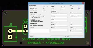
DipTrace is a sophisticated schematic and PCB layout software. I had it installed on my computer for over a year but have never really used it. Since I needed a super simple PCB for some 78XX / 79XX type linear regulators, I decided to use this opportunity for my first steps with DipTrace. DipTrace offers … [Read more…]